
 WhatsApp: +86 16626708626
 Email:
  Phone: +86 16626708626
Description
Key Technical Specifications
| Parameter | Value |
|---|---|
| Product Type | Analog Interface Module (IFM) |
| Catalog Number | 1492-AIFM8-3 |
| Product Family | Bulletin 1492 Connection Products |
| Interface Style | Feed-Through |
| Terminal Block | Fixed Terminal Block |
| Analog Channels | 8 Input or Output Channels |
| Field Wiring | 3 Terminals per I/O Channel |
| Cable Interface | 25-Pin D-Sub Connector |
| Voltage Rating | 0…132 V AC/DC |
| Maximum Current (Per Circuit) | 2 A |
| Maximum Current (Per Module) | 12 A |
| Maximum Recurring Peak Voltage | 600 V Peak |
| Operating Temperature | 0…60 °C |
| Operating Humidity | 5…95% RH (Non-condensing) |
| Approximate Weight | 290 g (0.64 lb) |
| Country of Origin | Mexico |
The 1492-AIFM8-3 is an active Rockwell Automation wiring interface module designed to simplify field wiring between PLC analog I/O modules and plant instrumentation. It provides eight analog input or output channels using a feed-through design with three terminals per channel.
Product Introduction
The Allen-Bradley 1492-AIFM8-3 is an eight-channel Analog Interface Module (IFM) used in Bulletin 1492 programmable controller wiring systems. Rather than performing signal conversion, it serves as a structured termination point between analog I/O modules and field devices, reducing wiring time and simplifying maintenance.
The module uses a fixed terminal block and a 25-pin D-shell connector, making it suitable for pre-wired cable assemblies used with numerous ControlLogix and CompactLogix analog modules. Because wiring remains organized at the interface module, replacing an I/O card typically requires minimal field rewiring, helping reduce maintenance downtime.
Installation & Configuration Guide
Stage 1 – Pre-Installation Preparation (10 Minutes)
⚠️ Safety First
- Shut down the control cabinet following Lockout/Tagout procedures.
- Verify all control power is isolated.
- Wear an ESD wrist strap before handling wiring components.
- Review the wiring diagram for the connected analog I/O module.
Required Tools
- Small flat-blade screwdriver
- Wire markers
- Digital multimeter
- Torque screwdriver
- ESD wrist strap
Before Installation
- Record existing terminal assignments.
- Photograph field wiring.
- Verify the connected PLC analog module catalog number.
- Inspect the D-shell cable for damage.
Stage 2 – Remove Existing IFM (5–10 Minutes)
- Disconnect the pre-wired cable.
- Label field wiring if necessary.
- Loosen terminal screws.
- Remove the interface module from the DIN rail.
- Inspect terminals for corrosion or overheating.
⚠️ Keep the original wiring layout until commissioning has been completed successfully.
Stage 3 – Install the New Module (10 Minutes)
- Confirm the replacement part number is 1492-AIFM8-3.
- Mount the module securely on the DIN rail.
- Connect the 25-pin D-shell cable.
- Reconnect all field wiring according to the wiring diagram.
- Tighten terminals to the recommended torque.
Installation Checklist
- ✅ Correct catalog number
- ✅ D-shell connector fully secured
- ✅ Terminal screws tightened
- ✅ Shield wiring correctly terminated
- ✅ Grounding verified
Stage 4 – Commissioning & Testing (10 Minutes)
- Restore cabinet power.
- Verify analog signals at the PLC.
- Confirm all channels respond correctly.
- Check for open circuits or incorrect polarity.
- Validate field instrument readings against expected values.
⚠️ If one or more analog channels read incorrectly, inspect the D-shell connector pinout and confirm the pre-wired cable matches the connected PLC analog module before replacing hardware.
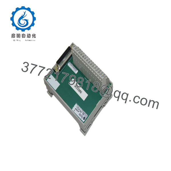
1492-AIFM8-3
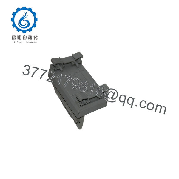
1492-AIFM8-3
Frequently Asked Questions
Can the 1492-AIFM8-3 process analog signals?
No. This module does not perform signal conditioning or A/D conversion. It is strictly a wiring interface that connects field devices to compatible PLC analog I/O modules.
Which PLC modules is it commonly used with?
It is commonly paired with compatible Allen-Bradley analog input and output modules through pre-wired D-shell cables, including ControlLogix and CompactLogix wiring systems supported by Bulletin 1492 documentation. Always verify cable and module compatibility before ordering.
Is the terminal block removable?
No. The 1492-AIFM8-3 uses a fixed terminal block. If a removable field terminal block is required, consider the 1492-RAIFM8-3 version instead.
Does replacing this IFM affect PLC programming?
No. The interface module contains no processor or memory. Replacing it does not alter PLC logic or analog module configuration.
Why are my analog values unstable after replacement?
The most common causes include:
- Incorrect D-shell cable selection
- Loose terminal connections
- Shield grounding errors
- Swapped channel wiring
- Field transmitter wiring faults
In practice, these issues are much more common than a defective interface module.
Is the 1492- still available?
Yes. Rockwell Automation currently lists the 1492- as an Active product with an estimated lead time of approximately five days, although availability may vary by region.



