
 WhatsApp: +86 16626708626
 Email:
  Phone: +86 16626708626
Description
Key Technical Specifications
| Parameter | Value |
|---|---|
| Product Type | Modular PLC Chassis |
| Catalog Number | 1746-A7 |
| Product Family | SLC 500 |
| Number of Slots | 7 |
| Mounting Method | Panel Mount |
| Backplane Current | 5.1 VDC @ 10 A; 24 VDC @ 2.88 A |
| Dimensions (W × H × D) | 282 × 171 × 145 mm (11.3 × 6.8 × 5.8 in.) |
| Approximate Weight | 1.1 kg (2.4 lb) |
| Operating Temperature | 0 to 60 °C |
| Storage Temperature | -40 to 85 °C |
| Relative Humidity | 5–95% non-condensing |
| Product Status | Discontinued (March 31, 2024) |
The Allen-Bradley 1746-A7 is a seven-slot modular chassis for SLC 500 systems. It provides the mechanical mounting structure and backplane connections for processors, power supplies, communication modules, and I/O modules. Rockwell Automation discontinued the product on March 31, 2024, with no direct Rockwell replacement planned.
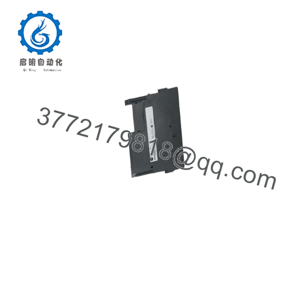
1746-A7
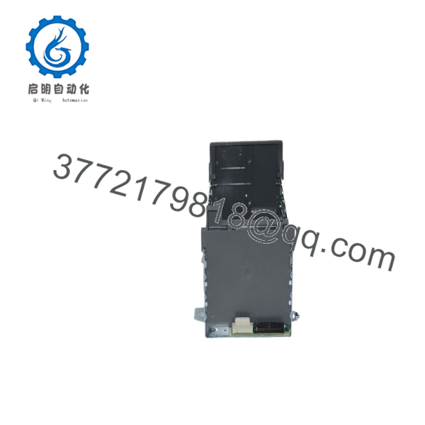
1746-A7
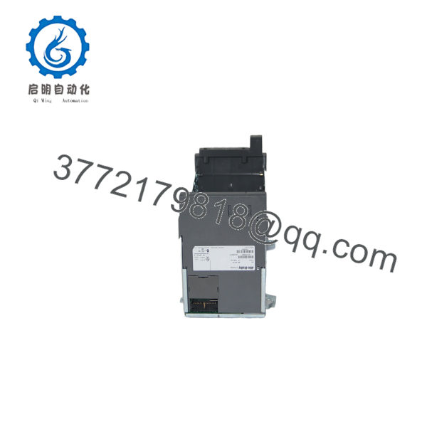
1746-A7
Product Introduction
The Allen-Bradley 1746-A7 is a modular chassis designed for the SLC 500 PLC platform. It accommodates one processor or communication adapter together with up to six additional I/O or specialty modules, making it suitable for machine automation, process control, packaging equipment, water treatment, and material handling systems.
Unlike an I/O module, the chassis does not perform control functions. Its role is to distribute backplane power and establish communication between installed modules. In existing SLC 500 installations, replacing a damaged chassis while retaining the original processor and I/O modules is often the most economical way to restore production without a complete system migration.
Installation & Configuration Guide
Stage 1 – Pre-Installation Preparation (10 Minutes)
⚠️ Safety First
- Notify operations personnel of scheduled downtime.
- Perform Lockout/Tagout procedures.
- Disconnect incoming power and wait at least five minutes.
- Verify all backplane voltages have discharged using a calibrated multimeter.
Required Tools
- ESD wrist strap
- Phillips screwdriver
- Torque screwdriver
- Digital multimeter
- Wire labels
- Smartphone for wiring documentation
Before Removal
- Back up the PLC program.
- Record chassis slot assignments.
- Photograph all module positions.
- Label communication and field wiring.
Stage 2 – Remove the Existing Chassis (15 Minutes)
- Remove field wiring from removable terminal blocks where applicable.
- Remove each module individually and keep them in slot order.
- Disconnect the chassis power supply.
- Remove chassis mounting screws.
- Inspect the mounting surface and backplane connectors.
⚠️ Do not mix module positions during reinstallation. Many SLC applications rely on fixed slot addressing.
Stage 3 – Install the New Chassis (15 Minutes)
- Verify the replacement catalog number is 1746-A7.
- Secure the chassis to the mounting panel.
- Install the power supply.
- Reinstall modules in their original slots.
- Reconnect communication cables and field wiring.
Installation Checklist
- ✅ Correct chassis installed
- ✅ Modules returned to original slots
- ✅ Power supply fully seated
- ✅ Ground connection verified
- ✅ All retaining tabs locked
Stage 4 – Power-Up & Functional Testing (15 Minutes)
- Verify there are no short circuits.
- Apply power to the chassis.
- Confirm power supply LED status.
- Verify processor startup.
- Confirm communication with all installed I/O modules.
- Check for slot or backplane faults.
- Test field I/O before returning the system to production.
⚠️ If multiple modules report communication faults simultaneously, inspect the chassis backplane connectors and ensure every module is fully seated before replacing additional hardware.
Frequently Asked Questions
Can I replace only the chassis and keep my existing modules?
Yes. That is the most common repair method. If the processor, power supply, and I/O modules are functional, they can typically be transferred directly into the replacement 1746-A7 chassis while preserving the original slot order.
Is the 1746-A7 still manufactured?
No. Rockwell Automation discontinued the 1746-A7 on March 31, 2024 and has announced no planned direct replacement. Most available units today are New Surplus or professionally refurbished inventory.
Can the chassis be expanded?
Yes. SLC 500 systems support multiple interconnected chassis using 1746 chassis interconnect cables, allowing expansion beyond a single rack, subject to SLC 500 architecture limits.
Will replacing the chassis erase my PLC program?
No. The application program is stored in the processor, not in the chassis. As long as the processor remains unchanged, replacing the chassis does not affect the PLC program.
What is the most common installation mistake?
The most frequent issue is installing modules in the wrong slots. Since SLC 500 systems use fixed slot addressing, moving an I/O module to a different position can generate I/O faults and prevent the application from operating correctly.
What should I inspect before ordering a replacement chassis?
Verify:
- Exact catalog number (1746-A7)
- Number of required slots
- Power supply compatibility
- Existing module configuration
- Mounting dimensions
- Chassis condition (new surplus or refurbished)
Taking a few minutes to confirm these details before ordering can prevent unnecessary downtime and avoid compatibility issues during installation.



