
 WhatsApp: +86 16626708626
 Email:
  Phone: +86 16626708626
Description
Key Technical Specifications
| Parameter | Value |
|---|---|
| Product Type | Digital AC Input Module |
| Catalog Number | 1746-IM16 |
| Product Family | SLC 500 |
| Number of Inputs | 16 |
| Input Voltage Range | 170–265 VAC |
| Nominal Voltage | 200/240 VAC |
| Input Frequency | 47–63 Hz |
| Points per Common | 16 |
| Backplane Current | 85 mA @ 5 VDC |
| Signal Delay | ON: 35 ms, OFF: 45 ms |
| Off-State Voltage (Max.) | 50 VAC |
| Off-State Current (Max.) | 2 mA |
| Isolation | 1,500 VAC backplane isolation |
| Operating Temperature | 0 to 60 °C |
The 1746-IM16 is a 16-point AC input module for the SLC 500 platform. It is designed for 200/240 VAC field signals and provides one input word to the controller through the SLC backplane.
Product Introduction
The Allen-Bradley 1746-IM16 interfaces 200/240 VAC field devices with SLC 500 PLC systems. Typical applications include monitoring selector switches, limit switches, relay contacts, motor starters, and auxiliary contacts operating on higher AC control voltages found in industrial equipment.
Unlike analog or output modules, the 1746-IM16 is dedicated to detecting discrete AC input states. It installs in any compatible SLC 500 chassis and communicates through the chassis backplane, making it suitable for machine automation, material handling, packaging, and process control systems that continue to operate legacy SLC 500 hardware.
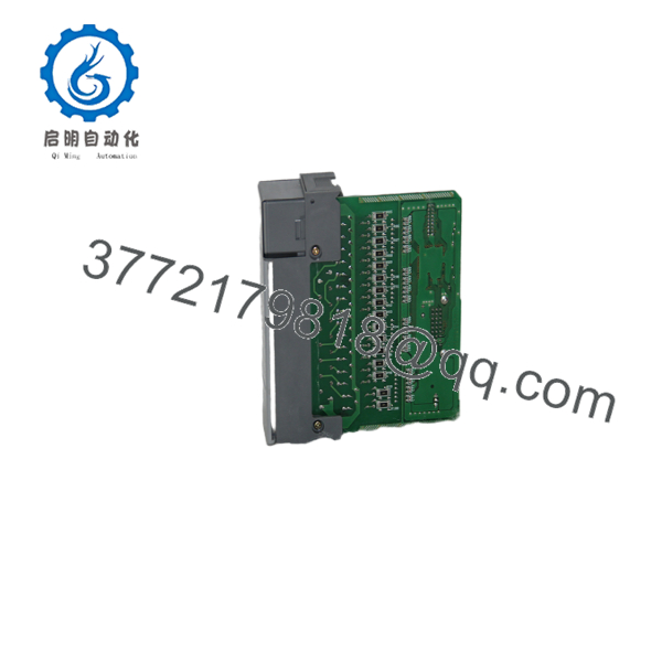
1746-IM16
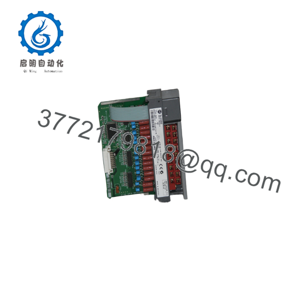
1746-IM16
Installation & Configuration Guide
Stage 1 – Pre-Installation Preparation (10 Minutes)
⚠️ Safety First
- Notify production personnel of scheduled downtime.
- Apply Lockout/Tagout procedures.
- Disconnect cabinet power and wait at least five minutes.
- Verify the AC control circuit is de-energized using a calibrated multimeter.
Required Tools
- ESD wrist strap
- Phillips screwdriver
- Digital multimeter
- Wire labels
- RSLogix 500 (for I/O verification)
Before Removal
- Upload and save the PLC program.
- Record the module slot location.
- Photograph field wiring.
- Label each conductor before disconnecting.
Stage 2 – Remove the Existing Module (10 Minutes)
- Remove field wiring from the terminal block.
- Release the module locking tabs.
- Pull the module straight from the chassis.
- Inspect the backplane connector for bent pins or contamination.
- Check the terminal block for loose or damaged terminals.
⚠️ Keep the original module available until the replacement has been fully commissioned.
Stage 3 – Install the New Module (10 Minutes)
- Verify the replacement catalog number is 1746-IM16.
- Wear an ESD wrist strap.
- Insert the module firmly into the chassis.
- Reconnect all field wiring according to the wiring diagram.
- Tighten terminal screws to the recommended torque.
Installation Checklist
- ✅ Correct module installed
- ✅ 200/240 VAC field voltage verified
- ✅ Wiring matches documentation
- ✅ Module fully seated
- ✅ Protective earth confirmed
Stage 4 – Power-Up & Functional Testing (10 Minutes)
- Restore chassis power.
- Confirm the processor enters RUN mode.
- Observe the input status LEDs.
- Operate each field device and verify the corresponding PLC input bit changes state.
- Test every input channel before returning the machine to service.
⚠️ If all channels remain OFF, verify that the field voltage is within the 170–265 VAC operating range and that the AC common wiring is correct before replacing the module. Incorrect field wiring is a more common cause of commissioning issues than module failure.
Frequently Asked Questions
Can the 1746-IM16 accept 120 VAC inputs?
No. The is designed specifically for 170–265 VAC input signals. For 100/120 VAC applications, the 1746-IA16 is the appropriate module.
Does this module require PLC programming changes when replacing an existing unit?
No. If you are replacing another in the same slot, no logic modifications are normally required. Verify the slot assignment and test each input after installation.
Can I hot-swap the 1746-?
No. The SLC 500 platform does not support hot swapping for this module. Always remove system power before installing or removing the module to protect the backplane and connected equipment.
What devices are commonly connected to this module?
Typical field devices include:
- 230 VAC selector switches
- Limit switches
- Relay auxiliary contacts
- Motor starter feedback contacts
- Control panel push buttons operating at 200/240 VAC
What is the most common installation mistake?
The most frequent issue is applying 120 VAC control voltage to a 240 VAC input module. The voltage is too low to reliably register an ON state, which often leads technicians to suspect a faulty module when the actual problem is a voltage mismatch.
What should I verify before ordering?
Confirm the following:
- Exact catalog number ()
- Required field voltage (170–265 VAC)
- SLC 500 chassis compatibility
- Available slot position
- Terminal block condition
- Existing wiring configuration
Verifying these items before purchase helps minimize installation delays and reduces the risk of ordering the wrong AC input module.



