
 WhatsApp: +86 16626708626
 Email:
  Phone: +86 16626708626
Description
3. Key Technical Specifications
| Parameter | Value |
|---|---|
| Catalog Number | 1746-NT4 |
| Module Type | 4-Channel Thermocouple/mV Analog Input |
| Number of Channels | 4 (backplane isolated) |
| Supported Thermocouple Types | J, K, T, E, R, S, B, N |
| Millivolt Ranges | ±50 mV DC, ±100 mV DC |
| A/D Conversion | Sigma-Delta |
| Resolution | 16-bit |
| Backplane Current | 60 mA @ 5 V DC, 40 mA @ 24 V DC |
| Backplane Power | 0.8 W max (0.3 W @ 5 V, 0.5 W @ 24 V) |
| Isolation | 500 V DC continuous (inputs to backplane/chassis) |
| Channel-to-Channel Separation | Series B or later: 2 V max; Series A: 0 V |
| Input Filter Frequencies | 10 Hz, 50 Hz, 60 Hz, 250 Hz |
| Update Time | 26 ms to 1.2 s (depends on filter and enabled channels) |
| Cold Junction Compensation | Integrated CJC sensors on terminal block |
| Operating Temperature | 0 °C to 60 °C (32 °F to 140 °F) |
| Storage Temperature | −40 °C to 85 °C (−40 °F to 185 °F) |
| Chassis Location | Any I/O slot except slot 0 |
| Terminal Block | Removable, 1746-RT32 |
| Module ID Code | 3510 |
| Weight | Approx. 0.28 kg (0.63 lb) |
4. Product Introduction
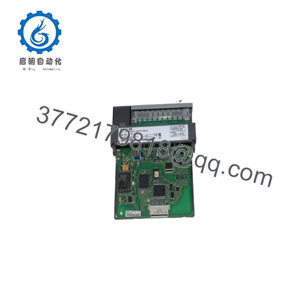
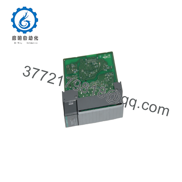
The Allen-Bradley 1746-NT4 is a 4-channel thermocouple/millivolt analog input module for the SLC 500 platform. It converts signals from thermocouple types J, K, T, E, R, S, B, and N, plus direct ±50 mV and ±100 mV inputs, into digital data available in the processor image table. Each channel is individually configurable for input type, data format, open-circuit response, temperature units, and filter frequency.
Field deployments of SLC 500 systems rely on this module for temperature monitoring where high common-mode rejection and cold-junction compensation are required. Series B and later units provide up to 2 V channel-to-channel common-mode separation. Configuration occurs entirely through ladder logic; the module has no DIP switches. Autocalibration runs at power-up and whenever a channel is enabled.

- 1746-NT4
- 1746-NT4
5. Installation & Configuration Guide
Stage 1: Pre-Installation Preparation (5–10 minutes) ⚠️ Safety First: Notify operations of planned downtime. Place the process in a safe state. Lock out/tag out all power sources to the chassis. Wait at least 5 minutes for capacitors to discharge. Tools Required: Grounded ESD wrist strap, PH1 screwdriver, digital multimeter, wire labels or markers, smartphone or camera for reference photos. Data Backup: Export the current RSLogix 500 project. Document the module’s slot number and any existing configuration words. Photograph the terminal block wiring and the old module’s label (including series letter). Note the processor series and firmware revision.
Stage 2: Removing the Old Module (5–8 minutes)
- Remove the front cover or door if present.
- Label every wire on the removable terminal block, then carefully disconnect them. Do not pull on the conductors.
- Release the self-locking tabs on the top and bottom of the module and pull it straight out of the chassis. Avoid rocking the module to protect the backplane connectors.
- Inspect the chassis backplane pins for bent contacts or debris. ⚠️ Keep the old module and its terminal block available until the new unit is verified and running under process conditions.
Stage 3: Installing the New Module (8–12 minutes)
- Put on the ESD wrist strap and ground it. Confirm the replacement module is exactly 1746-NT4 and note the series letter (A or B).
- Configuration Clone (Critical): There are no DIP switches or jumpers on the 1746-NT4. All settings are written by ladder logic to the module’s output image (configuration words). Record the old configuration words from the project or from the input status words before removal.
- Seat the new module firmly into the same chassis slot until the locking tabs click.
- Reinstall the removable terminal block (1746-RT32 or equivalent) and reconnect the thermocouple or mV wiring exactly as photographed. Observe correct polarity and use the proper thermocouple extension wire. Torque terminal screws to the recommended value; do not overtighten. Self-Checklist: [ ] Module series matches application needs [ ] Wiring polarity and type correct [ ] Terminal block fully seated [ ] Locking tabs engaged
Stage 4: Power-On & Testing (10–15 minutes) Pre-Power Check: With a multimeter, verify no short circuits exist between the 24 V and 5 V rails and chassis ground. Power-On Steps:
- Restore power to the chassis only (field devices still isolated if possible).
- Observe the five green status LEDs: module status LED should illuminate steady after self-test; each enabled channel LED should be steady green when the channel is healthy. Blinking indicates an open circuit, over-range, or under-range condition.
- Connect the programming terminal, go online with RSLogix 500, and verify the module appears in the I/O configuration with the correct ID code (3510).
- Write the previous configuration words to the module’s output image for each channel (input type, data format, open-circuit select, temperature units, filter frequency, and enable bit).
- Enable the channels and perform a dry-run comparison of readings against known temperature sources or a calibrated mV simulator. ⚠️ Troubleshooting Note: Solid red or missing module status LED usually indicates a backplane seating or power issue. Persistent open-circuit indications after wiring verification often point to a missing or failed CJC sensor on the terminal block, incorrect filter setting, or thermocouple polarity reversal. If Series A and Series B modules are mixed in the same system, confirm channel-to-channel common-mode voltage stays within the lower (Series A) limit of 0 V.
6. Frequently Asked Questions (FAQ)
Q: Can the 1746-NT4 be hot-swapped under power? No. Removing or inserting the module with chassis power applied risks damaging the backplane connectors and the module itself. Always kill power, wait for discharge, then swap.
Q: Is the 1746-NT4 obsolete, and is stock genuinely new? Yes, Rockwell discontinued the 1746-NT4 (EOL announced years ago). Available units are typically new surplus or carefully tested new-old-stock. Series B is preferred when channel-to-channel isolation matters. Verify series letter and date code on the label before installation.
Q: What is the recommended direct replacement if 1746-NT4 stock is exhausted? The closest SLC 500 form-factor alternative is the 1746-NT8 (8-channel version). For new designs, Rockwell points users toward CompactLogix or ControlLogix thermocouple modules (e.g., 1769-IT6 or 1756-IT6I). Wiring, configuration words, and image table layout will change, so plan a program and terminal revision.
Q: Will I lose my ladder logic or configuration when I replace the module? The processor retains the user program. Channel configuration, however, lives in the module’s output image words and must be rewritten after the swap. Always keep a documented copy of the configuration words or the RSLogix 500 project.
Q: Why is the price often lower than current Rockwell list prices? Because the module has been obsolete for years. New surplus and tested stock from authorized or reputable surplus channels typically sell below original factory list. Condition, series, and included terminal block affect pricing.
Q: Does the module require external power or special terminal blocks? It draws all power from the SLC 500 backplane (5 V and 24 V). The removable terminal block is catalog 1746-RT32; the two CJC sensors are mounted on that block. A missing or damaged CJC sensor produces large temperature errors.
Q: Are there firmware or series compatibility issues I should watch for? Series A modules have zero channel-to-channel common-mode separation; Series B and later allow 2 V. Mixing series in the same chassis with grounded thermocouples can cause measurement errors. Confirm the series letter matches the existing installation or the application’s common-mode requirements. Configuration is software-only, so processor firmware must support Class 1 analog modules.



