
 WhatsApp: +86 16626708626
 Email:
  Phone: +86 16626708626
Description
3. Key Technical Specifications
| Parameter | Value |
|---|---|
| Catalog Number | 1746-OW16 |
| Module Type | 16-Point Relay Contact Output (N.O.) |
| Number of Outputs | 16 |
| Points per Common | 8 (two groups) |
| Voltage Category | AC/DC Relay |
| Operating Voltage Range | 5–265 V AC (47–63 Hz) / 5–125 V DC |
| Continuous Current per Module | 16 A AC (8 A per common) |
| Continuous Current per Point | See contact ratings below |
| Signal Delay (Resistive Load) | On = 10.0 ms; Off = 10.0 ms |
| Off-State Leakage | 0 mA |
| Minimum Load Current | 10 mA @ 5 V DC |
| Backplane Current | 0.170 A @ 5 V DC; 0.180 A @ 24 V DC |
| Isolation | Optical isolation between field and backplane |
| Operating Temperature | 0 °C to 60 °C (32 °F to 140 °F) |
| Storage Temperature | −40 °C to 85 °C (−40 °F to 185 °F) |
| Chassis Location | Any I/O slot except slot 0 |
| Terminal Block | Removable |
| Weight | Approx. 0.45 kg (1.00 lb) |
Relay Contact Ratings (typical):
| Voltage | Make | Break | Continuous |
|---|---|---|---|
| 120 V AC | 15 A | 1.5 A | 2.5 A |
| 240 V AC | 7.5 A | 0.75 A | 2.5 A |
| 125 V DC | 0.22 A | 1.0 A | 1.0 A |
| 24 V DC | 1.2 A | 2.0 A | 2.0 A |
4. Product Introduction
The Allen-Bradley 1746-OW16 is a 16-point normally open (Form A) relay contact output module for the SLC 500 platform. It switches mixed AC and DC loads across a wide voltage range of 5–265 V AC or 5–125 V DC. Outputs are arranged in two groups of eight points sharing a common, allowing different voltage types on each group if required.
This module is selected when interposing relays would otherwise be needed or when mixed-voltage switching is required in a single slot. Zero off-state leakage and electromechanical contacts make it suitable for low-level and higher-power loads. Field experience shows contact life is extended significantly when proper surge suppression is applied to inductive loads. The module draws 170 mA from the 5 V backplane and 180 mA from the 24 V backplane.
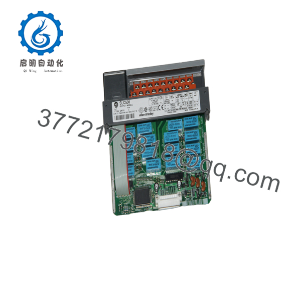
1746-OW16
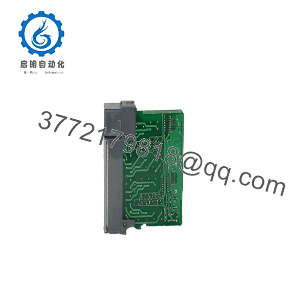
1746-OW16
5. Installation & Configuration Guide
Stage 1: Pre-Installation Preparation (5–8 minutes) ⚠️ Safety First: Notify operations of planned downtime. Place the process in a safe state. Lock out/tag out all power sources to the chassis and field devices. Wait at least 5 minutes for capacitors to discharge. Tools Required: Grounded ESD wrist strap, PH1 screwdriver, digital multimeter, wire labels, smartphone or camera for reference photos. Data Backup: Export the current RSLogix 500 project. Document the module slot number and existing output addresses. Photograph the terminal block wiring and the old module label (including series letter).
Stage 2: Removing the Old Module (5–7 minutes)
- Remove the front cover if present.
- Label every field wire on the removable terminal block, then carefully disconnect them. Do not pull on the conductors.
- Release the self-locking tabs on the top and bottom of the module and pull it straight out of the chassis. Avoid rocking the module to protect the backplane connectors.
- Inspect the chassis backplane pins for bent contacts or debris. ⚠️ Keep the old module available until the new unit is verified and running under process conditions.
Stage 3: Installing the New Module (6–10 minutes)
- Put on the ESD wrist strap and ground it. Confirm the replacement is exactly 1746-OW16.
- Configuration Note: The 1746-OW16 has no DIP switches or jumpers. Output behavior is controlled solely by the ladder program addressing the output image bits.
- Seat the new module firmly into the same chassis slot until the locking tabs click.
- Reinstall the removable terminal block and reconnect the field wiring exactly as photographed. Observe correct polarity and grouping. Apply appropriate surge suppression across inductive loads (RC snubbers for AC, diodes for DC). Self-Checklist: [ ] Wiring polarity and group commons correct [ ] Terminal block fully seated [ ] Locking tabs engaged [ ] Total current per common and module within ratings
Stage 4: Power-On & Testing (8–12 minutes) Pre-Power Check: With a multimeter, verify no short circuits exist between the field supplies and commons or chassis ground. Power-On Steps:
- Restore power to the chassis only (field devices still isolated if possible).
- Observe the module status and individual output LEDs. Each output LED should illuminate when the corresponding output bit is commanded ON.
- Connect the programming terminal, go online with RSLogix 500, and verify the module appears correctly in the I/O configuration.
- Force or toggle individual output bits and confirm field devices respond. Measure contact voltage drop under load if possible.
- Restore full field power and run a controlled process test. ⚠️ Troubleshooting Note: If an output LED is on but the field device does not energize, check field supply voltage, wiring, and load current. Relay contacts can weld or fail open under inductive switching without suppression. Exceeding the continuous current or VA limits shortens contact life. Module power must not exceed 1440 VA total.
6. Frequently Asked Questions (FAQ)
Q: Can the 1746-OW16 be hot-swapped under power? No. Inserting or removing the module with chassis power applied risks damaging the backplane connectors and the module. Always remove power first.
Q: Is the 1746-OW16 obsolete, and is stock genuinely new? Yes, the SLC 500 platform and this module have been discontinued by Rockwell. Available units are typically new surplus or carefully tested new-old-stock. Verify series letter and date code on the label before installation.
Q: What is the recommended direct replacement if 1746- stock is exhausted? Within the SLC 500 family the 1746-OX8 (individually isolated relays) or 1746-OW8 are partial alternatives. For new designs Rockwell directs users to CompactLogix or ControlLogix relay output modules (e.g., 5069-). Wiring, addressing, and contact ratings will differ, so plan a program and terminal revision.
Q: Will I lose my programming logic when I replace the module? The processor retains the user program. Output addresses remain the same provided the module stays in the same slot. No configuration words need to be rewritten because the 1746- has no programmable parameters.
Q: Why is the price often lower than original Rockwell list prices? Because the module has been obsolete for years. New surplus and tested stock from reputable channels typically sell below original factory list. Condition, series, and included terminal block affect pricing.
Q: Does this module require external surge suppression? Yes. Electromechanical relays benefit significantly from surge suppression on inductive loads. Use RC snubbers for AC loads and reverse-biased diodes for DC loads. Failure to suppress inductive kickback is a primary cause of premature contact welding or failure.
Q: What are the main current and voltage limitations I must respect? Continuous current is limited to 2.5 A per point on AC and 1–2 A on DC depending on voltage. Each common is limited to 8 A, and total module current must keep power under 1440 VA. Always apply the published make/break ratings for the specific voltage in use. Exceeding these values shortens contact life or causes immediate failure.



