
 WhatsApp: +86 16626708626
 Email:
  Phone: +86 16626708626
Description
Key Technical Specifications
| Parameter | Specification Value |
|---|---|
| Catalog Part Number | 1746SC-INO4I |
| Manufacturer | Spectrum Controls / Allen-Bradley Encompass |
| Compatible Architecture | Allen-Bradley SLC 500 (1746 I/O Chassis System) |
| Number of Channels | 4 individually isolated current outputs |
| Current Output Ranges | 0 to 20 mA, 4 to 20 mA (Software/DIP switch selectable) |
| Resolution | 16-bit (0.305 µA per LSB) |
| Channel-to-Channel Isolation | 500 V DC continuous |
| Backplane Power Draw | 120 mA @ 5 V DC, 250 mA @ 24 V DC |
| External Loop Voltage | 24 V DC nominal (18 to 30 V DC range per loop) |
| Update Time | < 5 ms across all channels |
| Operating Temperature | 0°C to +60°C (32°F to 140°F) |
| Terminal Connector | Removable Terminal Block (1746-RT25 compatible) |
Product Introduction & Supply Chain Strategy
The 1746SC-INO4I is a high-precision 4-channel isolated analog current output module engineered specifically for Allen-Bradley SLC 500 system racks. Built with 500 V DC channel-to-channel isolation, it drives critical control valves, positioners, and variable speed drives without ground loop distortion or cross-channel noise interference.
This product is a Brand New Surplus unit. It is not used, not pulled from a decommissioned plant, and not refurbished. All modules undergo rigorous quality verification to ensure OEM-level reliability.
Securing the 1746SC-INO4I as New Surplus provides key Total Cost of Ownership (TCO) benefits for legacy facilities. Buying verified New Surplus avoids the severe risks of refurbished modules—such as degraded digital-to-analog converter (DAC) chips or leaky isolation capacitors—while eliminating extended lead times on hard-to-find legacy SLC 500 hardware.
Installation & Configuration Guide
Stage 1: Pre-Installation (Prep & Safety)
- Open the main incoming AC power breaker feeding the SLC 500 rack and apply Lock-Out/Tag-Out (LOTO).
- Attach a grounded anti-static wrist strap connected to the enclosure frame ground terminal.
- Verify that module jumpers and address configuration DIP switches match the target slot configuration.
- Record terminal wiring connections on the existing 1746-RT25 removable terminal block before removal.
Stage 2: Removal
- Press the top and bottom releases on the 1746-RT25 removable terminal block and pull it straight forward.
- Press the upper and lower module retention tabs on the 1746SC-INO4I chassis card inward.
- Slide the board straight out along the chassis guide tracks to avoid twisting the rear backplane connector.
- Store the removed card inside an ESD shielding bag.
Stage 3: Installation (Clone & Seat)
- Confirm that DIP switch settings on the replacement 1746SC-INO4I card match the original module identically.
- Align the top and bottom edges of the card with the designated chassis card guides.
- Slide the card inward until the top and bottom retention tabs lock into the chassis frame with a distinct click.
- Re-insert the pre-wired removable terminal block until both side latches engage cleanly.
Stage 4: Power-On & Testing
- Re-apply power to the SLC 500 chassis power supply unit.
- Verify CPU and module status LEDs to confirm successful backplane initialization.
- Open RSLogix 500 to verify the slot configuration and ensure output data words transfer cleanly.
- Force test values in ladder logic to verify 4–20 mA current loops using a calibrated field meter.
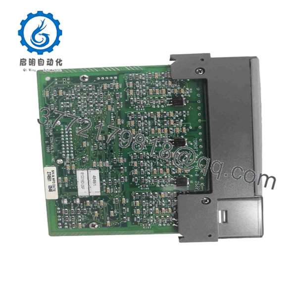
1746SC-INO4I
Firmware/Software Versions & Upgrade Notes
The 1746SC-INO4I maps directly into the SLC 500 memory image via standard output data registers.
- Software Compatibility: Fully supported in RSLogix 500 software versions 4.0 and higher using generic 1746 I/O setup profiles.
- Power Supply Headroom: Verify that the 24 V DC auxiliary rail on the chassis power supply (1746-P1, P2, or P4) has at least 250 mA of available current capacity to prevent backplane brownouts during 20 mA full-scale output.
- Fault State Settings: Match hardware DIP switch settings for module fault modes (e.g., hold last state vs. zero output) to maintain process safety upon communication failure.
Frequently Asked Questions (FAQ)
Q: Is this 1746SC- module brand new or has it been pulled from a decommissioned cabinet?
A: This product is a Brand New Surplus unit. It is not used, not pulled from a decommissioned plant, and not refurbished. All modules undergo rigorous quality verification to ensure OEM-level reliability.
Q: Why is New Surplus preferred over a cheaper refurbished analog card?
A: Our pricing reflects the cost of securing genuine New Surplus inventory globally. It may be 20–30% higher than a refurbished gamble, but it is substantially less than OEM list prices, and it buys you 100% peace of mind. Refurbished analog output cards often carry aged components that introduce calibration drift or signal ripple into sensitive control loops.
Q: Is the 1746SC- manufactured directly by Allen-Bradley or Spectrum Controls?
A: It is manufactured by Spectrum Controls as an official Allen-Bradley Encompass Partner product. It is engineered specifically for direct plug-and-play operation in Allen-Bradley SLC 500 racks.
Q: Does this module require an external 24 V DC loop power supply?
A: Yes. The 1746SC- requires external 24 V DC field loop power connected across its terminal block to drive isolated 4–20 mA signals to field devices.
Q: What warranty applies to this New Surplus module?
A: We back this card with a full 1-year functional replacement warranty from the date of shipment, ensuring continuous system protection and zero process downtime.



