
 WhatsApp: +86 16626708626
 Email:
  Phone: +86 16626708626
Description
Key Technical Specifications
| Parameter | Value |
|---|---|
| Product Type | SLC 5/02 Processor |
| Manufacturer | Allen-Bradley / Rockwell Automation |
| Model Number | 1747-L524 |
| Product Series | SLC 500 |
| User Memory | 4 KB (4,000 instructions) |
| Communication Port | DH-485 |
| Maximum Discrete I/O | 4,096 Inputs / 4,096 Outputs |
| Maximum Local Analog I/O | 480 Points |
| Maximum Local Chassis | 3 |
| Maximum Local I/O Slots | 30 |
| Program Scan Time | Approximately 1.6 ms/K instruction |
| Backup Memory | EEPROM Supported, Battery-backed RAM |
| Backplane Current | 350 mA @ 5 V DC |
| Backplane Current | 105 mA @ 24 V DC |
| Compatible Power Supplies | 1746-P1 through 1746-P7 |
| Operating Temperature | 0 to 60 °C |
The 1747-L524 is a discontinued SLC 5/02 controller with 4 KB user memory, native DH-485 communication, and support for up to three local chassis. It requires a compatible 1746-series power supply and supports EEPROM backup for program retention.
Product Introduction
The Allen-Bradley 1747-L524 is a member of the SLC 500 family and serves as the primary processor for small and medium industrial control systems. It executes ladder logic, manages local I/O, and communicates through its integrated DH-485 interface for programming and network communications.
Although Rockwell Automation discontinued this processor in 2017, many manufacturing facilities continue operating SLC 500 systems because of their proven reliability and stable application software. For maintenance departments supporting legacy equipment, the 1747-L524 remains an important spare processor for minimizing production downtime.
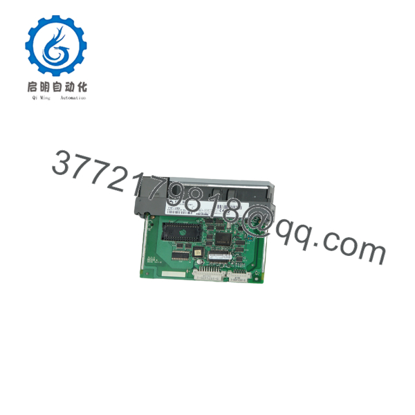
1747-L524
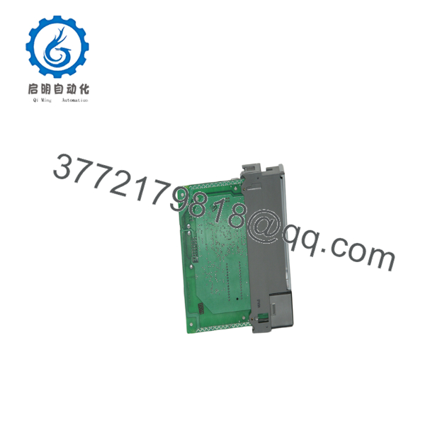
1747-L524
Installation & Configuration Guide
Stage 1 – Pre-Installation Preparation (Estimated Time: 10 Minutes)
⚠️ Safety First
- Notify operations personnel of the scheduled PLC shutdown.
- Bring all controlled equipment to a safe operating condition.
- Apply lockout/tagout procedures.
- Disconnect chassis power.
- Wait at least 5 minutes before removing the processor.
Tools Required
- Grounded ESD wrist strap
- PH1 screwdriver
- Fluke 115 digital multimeter
- Wire identification labels
- Smartphone for documentation
Data Backup
- Upload the complete RSLogix 500 project.
- Save the processor program and data files.
- Record processor communication parameters.
- Photograph every communication cable.
- Record EEPROM configuration if installed.
- Verify battery condition before removing the CPU.
Stage 2 – Removing the Existing Processor (Estimated Time: 10 Minutes)
- Confirm chassis power is OFF.
- Disconnect the DH-485 programming cable.
- Label all communication wiring.
- Release the processor locking tabs.
- Pull the CPU straight from the chassis.
- Inspect the backplane connector for bent pins or contamination.
⚠️ Do not discard the original processor until the replacement has successfully completed commissioning.
Stage 3 – Installing the Replacement Processor (Estimated Time: 10 Minutes)
- Wear a grounded ESD wrist strap.
- Verify the replacement catalog number is 1747-L524.
- Check battery installation and expiration date.
- Install the EEPROM if required.
- Carefully insert the processor into the chassis.
- Verify the locking tabs engage completely.
- Reconnect the communication cable.
- Restore the saved application if necessary.
Self-Checklist
- Correct processor installed
- EEPROM installed (if required)
- Battery verified
- Processor fully seated
- Communication cable connected
Stage 4 – Power-On & Testing (Estimated Time: 15 Minutes)
Pre-Power Checks
- Verify chassis power supply voltage.
- Confirm processor seating.
- Check communication cable connections.
Commissioning Steps
- Apply power to the chassis.
- Observe CPU LEDs during startup.
- Confirm the processor enters RUN mode.
- Connect using RSLogix 500.
- Verify the processor identity.
- Confirm the ladder program is present.
- Test critical machine functions before returning equipment to production.
⚠️ Troubleshooting Notes
- FLT LED ON: Check EEPROM compatibility, battery condition, and processor diagnostics.
- No communication: Verify DH-485 network addressing and cable integrity.
- Memory fault: Confirm the correct project was downloaded and EEPROM contents match the processor revision.
Common Field Pitfalls
❗ Firmware and Processor Revision
The SLC 5/02 platform predates many modern compatibility tools. Before replacing the CPU, document the processor revision and EEPROM contents. Installing a processor with different firmware behavior or an outdated EEPROM can generate unexpected startup faults.
❗ Battery Condition
I’ve seen maintenance teams replace a failed processor only to discover the replacement battery was already exhausted. The controller booted normally, but memory disappeared after the next power outage. Always install a fresh battery if its service history is unknown.
❗ Communication Configuration
The 1747-L524 communicates through DH-485 only. If the maintenance laptop cannot connect, verify the programming interface and node address before assuming the processor has failed.
❗ Power Supply Capacity
The processor requires approximately 350 mA at 5 V DC and 105 mA at 24 V DC from the SLC backplane. When adding additional analog or specialty modules, recalculate total chassis loading and maintain at least a 20% power margin.
❗ Electrostatic Discharge
CPU modules are among the most expensive components in an SLC chassis. Always handle the board by its edges while wearing a grounded wrist strap. One static discharge can permanently damage memory circuitry without leaving visible evidence.
Keep these checks in mind and you’ll avoid most of the commissioning delays encountered during SLC 500 processor replacements.
Frequently Asked Questions (FAQ)
Q1. Is the Allen-Bradley 1747- obsolete?
Yes.
Rockwell Automation discontinued the 1747- on January 31, 2017. Existing systems remain widely deployed, making New Surplus and professionally tested replacement units common choices for maintenance inventories.
Q2. Can I hot-swap the 1747- processor?
No.
The SLC 500 processor is not hot-swappable. Always remove chassis power before replacing the CPU. Removing or installing the processor under power can damage the backplane or corrupt controller memory.
Q3. Will replacing the processor erase my application program?
Possibly.
If the existing processor contains the only copy of the application, replacing it without first uploading the project can result in data loss. Always create an RSLogix 500 backup and verify whether an EEPROM is installed before removing the CPU.
Q4. What is the direct replacement for the 1747-?
There is no direct plug-and-play successor with identical specifications. Facilities typically replace a failed unit with another or migrate to a higher-capacity SLC 5/03, 5/04, or 5/05 processor after evaluating communication requirements, memory usage, and application compatibility.
Q5. Why are New Surplus units less expensive than historical OEM pricing?
Most New Surplus inventory comes from canceled projects, warehouse overstock, or unused maintenance inventory. Lower pricing generally reflects the product’s lifecycle status rather than its operating capability. Always request inspection records, functional test reports, and warranty information before purchasing.
Q6. How is every processor inspected before shipment?
Our inspection process follows a documented workflow:
- Inbound Inspection & Traceability
- Verify OEM labels and serial numbers.
- Inspect for corrosion, repair marks, UV discoloration, or connector damage.
- Confirm accessories and documentation where available.
- Functional Testing
- Install the processor in a genuine SLC 500 test chassis.
- Verify power-up sequence and LED indications.
- Establish DH-485 communication.
- Download and execute a validation program.
- Run the processor continuously for more than 24 hours while monitoring stability.
- Electrical Verification
- Measure insulation resistance using a 500 V Megger.
- Perform ground continuity checks.
- Conduct dielectric testing where applicable.
- Configuration Verification
- Record firmware identification.
- Verify EEPROM operation if installed.
- Document battery status.
- Final QC
- Complete inspection records.
- Package the processor in an ESD bag with protective cushioning.
- Apply a dated QC inspection label.
Test photographs and operating videos can be provided upon request.
Q7. What should I verify before installing a replacement 1747-?
Before commissioning, verify:
- Exact catalog number ()
- Battery condition
- EEPROM compatibility
- DH-485 communication settings
- RSLogix 500 project backup
- Chassis power capacity
- Processor diagnostic LEDs
From field experience, the majority of startup problems are caused by missing backups, depleted batteries, or communication settings—not by defective processors themselves. Spending ten minutes documenting the original installation can eliminate hours of troubleshooting later.



