
 WhatsApp: +86 16626708626
 Email:
  Phone: +86 16626708626
Description
Key Technical Specifications
| Parameter | Value |
|---|---|
| Product Type | SLC 5/04 Processor |
| Manufacturer | Allen-Bradley / Rockwell Automation |
| Model Number | 1747-L542 |
| Product Series | SLC 500 |
| User Memory | 32 KB |
| Program Scan Time | Typical 0.9 ms/K word |
| I/O Scan Time | Typical 0.225 ms |
| Maximum Local Chassis | 3 |
| Maximum Local I/O Slots | 30 |
| Maximum Digital I/O | 4,096 Inputs / 4,096 Outputs |
| Maximum Analog I/O | 480 Points |
| Communication Ports | Channel 0: RS-232 (DF1, DH-485, ASCII); Channel 1: DH+ |
| Supported Protocols | DF1 Full/Half Duplex, DH-485, ASCII, Modbus RTU Master |
| Backup Memory | Battery-backed RAM, Optional 1747-M13 Memory Module |
| Backplane Current | 1,000 mA @ 5 V DC; 175 mA @ 24 V DC |
| Operating Temperature | 0 to 60 °C |
| Storage Temperature | −40 to 85 °C |
| Relative Humidity | 5–95% non-condensing |
The 1747-L542 is an SLC 5/04 processor with 32 KB memory, dual communication channels (RS-232 and DH+), and support for up to three local chassis, making it suitable for medium-sized SLC 500 control systems.
Product Introduction
The Allen-Bradley 1747-L542 is a 32 KB SLC 5/04 processor designed for the SLC 500 family of programmable controllers. It executes ladder logic, manages local I/O, and provides integrated RS-232 and Data Highway Plus (DH+) communications for programming, HMI connectivity, and plant network integration.
From field experience, the 1747-L542 is commonly found in packaging, material handling, water treatment, and process manufacturing systems that continue to operate reliably decades after commissioning. Its dual communication channels simplify maintenance while allowing simultaneous programming and plant network communications.
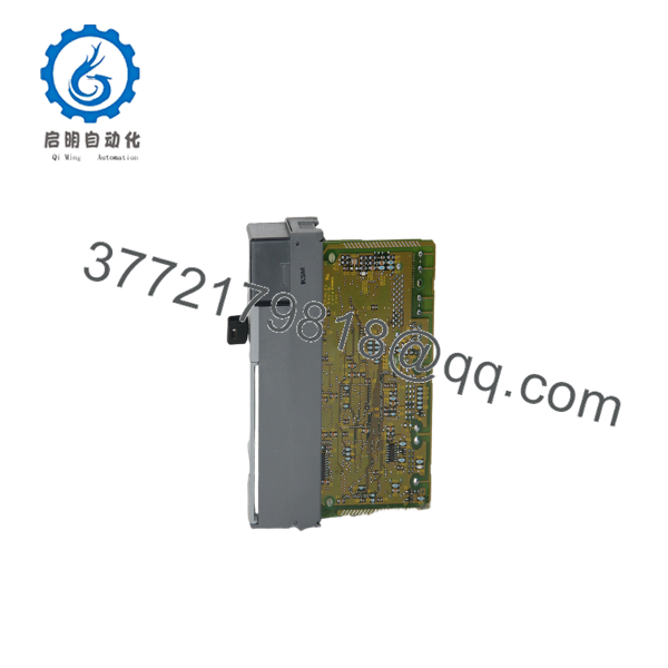
1747-L542
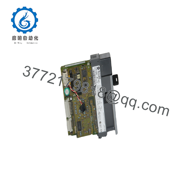
1747-L542
Installation & Configuration Guide
Stage 1 – Pre-Installation Preparation (Estimated Time: 10 Minutes)
⚠️ Safety First
- Notify production personnel of the planned shutdown.
- Bring all controlled equipment to a safe operating condition.
- Apply lockout/tagout procedures.
- Remove chassis power.
- Wait at least 5 minutes for internal capacitors to discharge.
Tools Required
- Grounded ESD wrist strap
- PH1 screwdriver
- Fluke 115 digital multimeter
- Wire identification labels
- Smartphone for recording wiring and switch positions
Data Backup
- Upload the complete RSLogix 500 project.
- Save processor program files and data tables.
- Record Channel 0 communication settings.
- Document DH+ node address.
- Photograph all communication cables.
- Verify battery condition and optional 1747-M13 memory module.
Stage 2 – Removing the Existing Processor (Estimated Time: 10 Minutes)
- Verify the chassis is completely de-energized.
- Disconnect RS-232 and DH+ communication cables.
- Label every cable before removal.
- Release the processor locking tabs.
- Pull the processor straight out to avoid damaging the backplane connector.
- Inspect the chassis connector for bent pins, dust, or oxidation.
⚠️ Keep the original processor until the replacement has completed functional testing.
Stage 3 – Installing the New Processor (Estimated Time: 10 Minutes)
- Wear a grounded ESD wrist strap.
- Verify the replacement is 1747-L542 with the correct hardware revision.
- Install the battery and optional memory module if required.
- Insert the processor fully into the chassis until the locking tabs engage.
- Reconnect communication cables.
- Restore the controller program if necessary.
- Verify communication parameters before switching the processor to RUN mode.
Self-Checklist
- Correct catalog number
- Battery installed
- Memory module verified
- Processor fully seated
- Communication cables connected
- Node address verified
Stage 4 – Power-On & Testing (Estimated Time: 15 Minutes)
Pre-Power Checks
- Measure chassis supply voltage.
- Verify processor seating.
- Confirm communication cable integrity.
Commissioning Procedure
- Apply power to the chassis.
- Observe the CPU LED sequence.
- Verify the processor reaches RUN mode.
- Connect using RSLogix 500 through Channel 0.
- Verify DH+ communications with HMIs or supervisory systems.
- Execute a controlled I/O verification before returning the machine to production.
⚠️ Troubleshooting Notes
- Solid FLT LED: Check battery condition, processor diagnostics, or incompatible memory module.
- No RS-232 communication: Verify baud rate, DF1 driver, and serial cable.
- DH+ offline: Confirm node address, network termination, and cable integrity.
- Program mismatch: Verify the downloaded project matches the original processor revision.
Common Field Pitfalls
❗ Firmware and Project Compatibility
I’ve seen technicians replace a failed processor with a spare from another production line without verifying firmware revision. The hardware powered up normally, but messaging instructions failed because the replacement had a different firmware revision. Always record the original revision before removing the CPU.
❗ Battery Replacement
Never assume the battery in a surplus processor is serviceable. Replace it if the installation date is unknown. Losing battery-backed memory during an unexpected outage creates unnecessary recovery work.
❗ Channel Configuration
The 1747-L542 supports several communication modes on Channel 0. Verify DF1, DH-485, or ASCII settings before assuming the processor has failed. Incorrect serial configuration remains one of the most common startup problems.
❗ Chassis Power Budget
The processor draws approximately 1,000 mA at 5 V DC and 175 mA at 24 V DC. Before adding specialty or analog modules, calculate total backplane loading and maintain at least a 20% reserve capacity.
❗ Electrostatic Discharge
Always handle the processor by its edges while wearing a grounded wrist strap. Static damage frequently affects memory or communication circuits without leaving visible physical evidence.
Keep these checks in mind and you’ll avoid most of the commissioning delays associated with SLC 5/04 processor replacements.
Frequently Asked Questions (FAQ)
Q1. Is the Allen-Bradley 1747- obsolete?
Yes. The 1747- belongs to the legacy SLC 500 platform. Although Rockwell Automation no longer recommends it for new installations, many production facilities continue supporting these processors because replacement hardware and engineering expertise remain available.
Q2. Can I replace the 1747- while power is on?
No.
The processor is not hot-swappable. Removing or inserting it under power can damage the backplane and interrupt all controller operations.
Q3. Will replacing the CPU erase my application?
Not if you prepare correctly.
Upload the complete RSLogix 500 project before removal. If a 1747-M13 memory module is installed and properly configured, program recovery is much easier. Otherwise, the processor should be restored from your engineering backup.
Q4. What communication ports are available?
The processor provides:
- Channel 0: RS-232 supporting DF1, DH-485, ASCII, and Modbus RTU Master
- Channel 1: Data Highway Plus (DH+)
This allows simultaneous programming and network communications in many legacy systems.
Q5. What is the direct replacement if this processor fails?
For minimal downtime, replacing the failed unit with another is generally the simplest option. If the facility is planning modernization, migration to a current CompactLogix platform requires engineering changes to hardware, communications, and application software rather than a direct hardware swap.
Q6. Why are New Surplus units often priced below the historical OEM list price?
Most New Surplus processors originate from canceled projects, warehouse overstock, or unused maintenance inventory. Pricing reflects product lifecycle status rather than operating capability. Always request functional test records, firmware identification, and warranty details before purchasing.
Q7. How is each processor verified before shipment?
Our inspection workflow follows a documented process:
- Inbound Inspection & Traceability
- Verify OEM labels, serial numbers, and product traceability.
- Inspect for corrosion, repairs, connector wear, and UV discoloration.
- Functional Testing
- Install the processor in a genuine SLC 500 chassis.
- Verify LED startup sequence.
- Test RS-232 and DH+ communications.
- Download and execute a validation application.
- Operate continuously for more than 24 hours while monitoring temperature and communication stability.
- Electrical Testing
- Measure insulation resistance using a 500 V Megger.
- Verify ground continuity.
- Perform dielectric testing where applicable.
- Firmware Verification
- Record firmware revision.
- Verify battery status.
- Test optional memory module operation.
- Final Quality Control
- QC inspector approval.
- ESD packaging.
- Heavy-duty protective carton.
- QC label with inspection date.
Test photographs and commissioning videos are available upon request.



