
 WhatsApp: +86 16626708626
 Email:
  Phone: +86 16626708626
Description
Key Technical Specifications
| Parameter | Value |
|---|---|
| Product Type | ControlLogix Chassis |
| Manufacturer | Allen-Bradley / Rockwell Automation |
| Model Number | 1756-A10 |
| Product Series | ControlLogix |
| Chassis Capacity | 10 Slots |
| Backplane Type | Passive high-speed backplane |
| Cooling Method | Natural convection |
| Mounting | Panel mount |
| Compatible Controllers | ControlLogix 55xx, 5560, 5570, 5580 Series |
| Compatible Power Supplies | 1756-PA72, 1756-PA75, 1756-PB72, 1756-PB75 and compatible ControlLogix power supplies |
| Supported Modules | CPU, I/O, Motion, Network, Safety, Process modules |
| Operating Temperature | 0 to 60 °C (Series B), up to -25 to 60 °C for newer Series C hardware |
| Relative Humidity | 5–95% non-condensing |
| Certifications | CE, ATEX, IECEx, RCM and other regional approvals depending on hardware revision |
Product Introduction
The Allen-Bradley 1756-A10 is a 10-slot ControlLogix chassis that serves as the mechanical mounting platform and passive backplane for ControlLogix controllers, I/O modules, communication modules, and specialty cards. The chassis itself performs no processing; it distributes power and high-speed backplane communications between installed modules.
In production facilities, the 1756-A10 is commonly used for medium-sized ControlLogix systems where future expansion is expected without moving to a larger 13-slot or 17-slot chassis. Proper power supply sizing and slot planning are far more important than the chassis itself because these decisions directly affect future maintenance and expansion.
Installation & Configuration Guide
Stage 1 – Pre-Installation Preparation (Estimated Time: 10 Minutes)
⚠️ Safety First
- Notify operations of the scheduled shutdown.
- Bring the controlled process to a safe state.
- Apply lockout/tagout procedures.
- Remove all ControlLogix chassis power.
- Wait at least 5 minutes for power supplies to discharge.
Tools Required
- Grounded ESD wrist strap
- PH1 screwdriver
- Fluke 115 digital multimeter
- Torque screwdriver
- Wire labels
- Smartphone for documentation
Data Backup
- Upload the Studio 5000 project.
- Save controller programs.
- Record slot assignments.
- Photograph module locations.
- Record IP addresses and network configuration.
- Label every communication cable before removal.
Stage 2 – Removing the Existing Chassis (Estimated Time: 20 Minutes)
- Verify all power supplies are OFF.
- Remove every communication cable.
- Label each module by slot number.
- Remove the power supply.
- Remove all ControlLogix modules individually.
- Unscrew the chassis mounting hardware.
- Inspect the mounting panel for damage or contamination.
⚠️ Never move modules into another chassis without recording their original slot positions. Slot numbering is referenced by the controller configuration.
Stage 3 – Installing the New Chassis (Estimated Time: 20 Minutes)
- Wear a grounded ESD wrist strap.
- Verify the replacement is 1756-A10.
- Secure the chassis to the mounting panel.
- Install the power supply.
- Reinstall every module into its documented slot.
- Verify every module is fully seated.
- Tighten mounting hardware according to the installation manual.
Self-Checklist
- Correct chassis installed
- Power supply secured
- Modules returned to correct slots
- Connectors fully seated
- Mounting screws tightened
Stage 4 – Power-On & Testing (Estimated Time: 20 Minutes)
Pre-Power Checks
- Measure incoming power supply voltage.
- Verify chassis grounding.
- Inspect every module latch.
- Confirm no empty connector contains debris.
Commissioning Steps
- Energize the ControlLogix power supply.
- Observe controller and communication module LEDs.
- Connect using Studio 5000 Logix Designer.
- Verify chassis size matches the project configuration.
- Confirm every module establishes communication.
- Test all critical I/O before returning the machine to service.
⚠️ Troubleshooting Notes
- If Studio 5000 reports “Module Not Present”, verify slot assignments before replacing hardware.
- If multiple modules fault simultaneously, inspect the backplane connector and verify power supply capacity.
- If the controller enters a major fault after startup, confirm the I/O configuration matches the physical chassis.
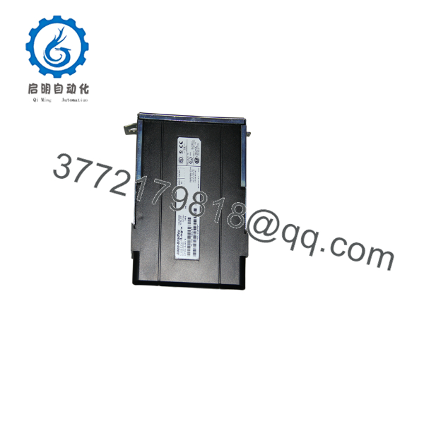
1756-A10
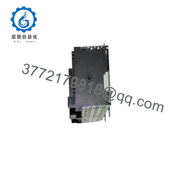
1756-A10
Common Field Pitfalls
❗ Slot Number Changes
This catches experienced engineers more often than new technicians. Someone reinstalls modules in different slots because “they all fit.” The controller immediately reports I/O faults. Always reinstall every module in its original slot unless the project has been modified accordingly.
❗ Chassis Series Compatibility
I’ve seen older installations upgraded with higher-capacity power supplies while retaining an early chassis revision. Verify the chassis hardware series is compatible with the selected power supply and installed modules before commissioning. Community field experience also notes that early Series A/B hardware has different power capabilities than later revisions.
❗ Power Supply Selection
The chassis itself does not generate power. Select a ControlLogix power supply that supports the combined current draw of every installed module while maintaining at least a 20% engineering margin.
❗ Backplane Connector Damage
Never force a module into the chassis. Bent guide rails or damaged connectors can create intermittent communication faults that resemble processor failures.
❗ Electrostatic Discharge
The passive backplane contains high-density communication connectors. Static discharge may not destroy the chassis immediately, but it can shorten connector life or damage installed electronics. Always use an ESD wrist strap.
Keep these checks in mind and you’ll avoid most of the downtime associated with ControlLogix chassis replacement.
Frequently Asked Questions (FAQ)
Q1. Is the Allen-Bradley 1756-A10 obsolete?
No.
The 1756-A10 remains an active ControlLogix product and continues to be supported by Rockwell Automation. It carries a standard one-year warranty when purchased through authorized channels.
Q2. Does the 1756-A10 include a power supply?
No.
The chassis is supplied separately from the power supply. A compatible 1756-PA (AC) or 1756-PB (DC) power supply must be selected according to the system power requirements.
Q3. Can I replace the chassis without changing the PLC program?
Yes.
The user application resides in the ControlLogix controller, not in the chassis. If every module is returned to the same slot and the controller remains unchanged, the application normally operates without modification.
Q4. Can I install any ControlLogix module in any slot?
Generally, yes.
Most I/O, communication, motion, and specialty modules may be installed in any available slot. However, maintain the slot assignments defined in the Studio 5000 project because the controller references modules by slot number.
Q5. Why is the 1756-A10 available as both New Original and New Surplus?
New Original inventory typically comes through authorized distribution. New Surplus inventory usually originates from unused project stock, canceled installations, or excess maintenance inventory. Verify the condition, hardware series, inspection records, and warranty before purchasing.
Q6. How is each chassis inspected before shipment?
Our inspection procedure includes:
- Inbound Inspection & Traceability
- Verify OEM labels and serial numbers.
- Inspect guide rails, connectors, and mounting surfaces.
- Check for corrosion, scratches, repairs, or UV discoloration.
- Functional Testing
- Install the chassis with a genuine ControlLogix power supply.
- Verify controller recognition.
- Test backplane communication using multiple I/O and communication modules.
- Operate continuously for more than 24 hours while monitoring stability.
- Electrical Verification
- Measure insulation resistance using a 500 V Megger.
- Verify chassis grounding.
- Inspect backplane continuity.
- Configuration Verification
- Record hardware revision.
- Verify connector integrity.
- Inspect mechanical alignment.
- Final QC & Packaging
- QC inspector approval.
- ESD protective packaging.
- Heavy-duty corrugated shipping carton.
- QC Passed label with inspection date.
Test photographs and functional test videos are available upon request.
Q7. What should I verify before installing a replacement 1756-A10?
Before commissioning, verify:
- Exact catalog number (1756-A10)
- Chassis hardware revision
- Compatible power supply
- Module slot assignments
- Backplane connector condition
- Chassis grounding
- Studio 5000 hardware configuration
From field experience, the chassis is rarely the source of ControlLogix failures. Most startup issues result from incorrect slot assignments, insufficient power supply capacity, or configuration mismatches rather than a defective backplane.



