
 WhatsApp: +86 16626708626
 Email:
  Phone: +86 16626708626
Description
Key Technical Specifications
| Parameter | Value |
|---|---|
| Product Type | ControlNet Bridge Module |
| Manufacturer | Allen-Bradley / Rockwell Automation |
| Model Number | 1756-CNB |
| Product Series | ControlLogix |
| Communication Protocol | ControlNet |
| ControlNet Port | 1 BNC connector |
| NAP Port | 1 RJ45 Network Access Port |
| Transmission Rate | 5 Mbps |
| Maximum Nodes | 99 |
| Maximum Logix Connections | 64 (typically 40–48 application connections) |
| Module Location | Any ControlLogix chassis slot |
| Current Draw | 970 mA @ 5.1 V DC, 1.7 mA @ 24 V DC |
| Power Dissipation | 5.1 W |
| Isolation Voltage | 30 V continuous, basic insulation |
| Operating Temperature | 0 to 60 °C |
| Storage Temperature | −40 to 85 °C |
| Relative Humidity | 5–95% non-condensing |
| Approximate Weight | 0.26 kg (0.57 lb) |
The 1756-CNB is a single-port ControlNet bridge module. Rockwell Automation lists it as discontinued with an end-of-sale date of December 31, 2024 and recommends the 1756-CN2 as the engineering replacement for new projects.
Product Introduction
The Allen-Bradley 1756-CNB is a ControlLogix communication module that provides a bridge between a ControlLogix chassis and a ControlNet network. It supports scheduled and unscheduled messaging for distributed I/O, peer-to-peer controller communications, HMIs, and other ControlNet devices.
Although ControlNet installations are becoming less common in new projects, many production facilities continue operating large installed networks because of their deterministic communication performance. For existing systems, replacing a failed 1756-CNB with an identical module is often the fastest method of restoring production without redesigning the network.
Installation & Configuration Guide
Stage 1 – Pre-Installation Preparation (Estimated Time: 10 Minutes)
⚠️ Safety First
- Notify operations personnel of the scheduled shutdown.
- Place the machine or process into a safe operating condition.
- Apply lockout/tagout procedures.
- Remove chassis power.
- Wait at least 5 minutes before removing the module.
Tools Required
- Grounded ESD wrist strap
- PH1 screwdriver
- Fluke 115 digital multimeter
- Torque screwdriver
- Cable identification labels
- Smartphone for recording network wiring
Data Backup
- Upload the Studio 5000 project.
- Save the ControlNet network configuration.
- Record the node address.
- Record the scheduled network configuration.
- Photograph all coaxial cable connections.
- Document ControlNet media redundancy configuration if applicable.
Stage 2 – Removing the Existing Module (Estimated Time: 10 Minutes)
- Verify the chassis is completely de-energized.
- Disconnect the ControlNet coaxial cable.
- Disconnect the NAP cable if installed.
- Label every communication cable.
- Release the module locking tabs.
- Pull the module straight from the chassis.
- Inspect the backplane connector for contamination or bent pins.
⚠️ Do not discard the original module until network communications have been verified.
Stage 3 – Installing the Replacement Module (Estimated Time: 10 Minutes)
- Wear a grounded ESD wrist strap.
- Verify the replacement catalog number is 1756-CNB.
- Confirm the hardware revision is compatible with the existing system.
- Insert the module fully into the ControlLogix chassis.
- Reconnect the ControlNet coaxial cable.
- Verify BNC connectors are fully locked.
- Restore the original network configuration if required.
Self-Checklist
- Correct catalog number
- Module fully seated
- ControlNet cable secured
- Node address verified
- Network configuration restored
Stage 4 – Power-On & Testing (Estimated Time: 20 Minutes)
Pre-Power Checks
- Verify chassis power supply capacity.
- Check ControlNet cable continuity.
- Inspect BNC connectors for damage.
- Confirm network terminators remain installed.
Commissioning Steps
- Apply power to the ControlLogix chassis.
- Observe the module status indicators.
- Verify the module appears online in Studio 5000.
- Confirm ControlNet network status.
- Verify all scheduled I/O connections.
- Test controller messaging and remote I/O.

1756-CNB
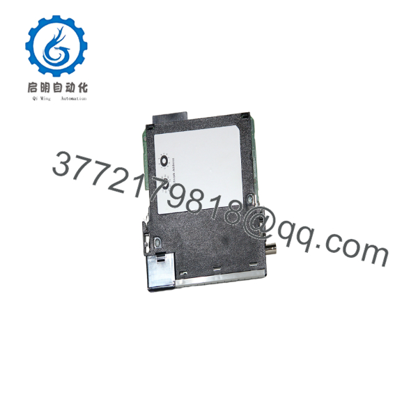
1756-CNB
⚠️ Troubleshooting Notes
- NET LED flashing red: Check node address conflicts or damaged coaxial cable.
- Module fault: Verify firmware revision and hardware compatibility.
- Remote I/O offline: Confirm the ControlNet schedule has been restored and the network is synchronized. Rockwell ControlNet systems may require the network schedule to be transferred or re-established after module replacement, depending on the network architecture. Community experience indicates that systems with a designated Keeper may restore scheduling automatically, while others require re-scheduling with RSNetWorx for ControlNet.
Common Field Pitfalls
❗ Firmware Revision Differences
A replacement module with a different firmware revision may not immediately establish scheduled connections. Before replacing the hardware, record the original firmware revision whenever possible.
❗ ControlNet Network Scheduling
This catches many maintenance teams. Installing a replacement module does not always restore scheduled communication automatically. If no Keeper device exists on the network, you may need to download or re-schedule the ControlNet configuration before I/O resumes.
❗ Coaxial Cable Problems
ControlNet uses RG-6 quad-shield coaxial cable. Damaged BNC connectors, loose taps, or poor cable shielding often produce intermittent communication faults that resemble module failures.
❗ Backplane Power Capacity
The module draws approximately 970 mA at 5.1 V DC. Before installing additional communication modules, verify total chassis power consumption and maintain approximately a 20% engineering reserve.
❗ Electrostatic Discharge
Communication ASICs are highly sensitive to static discharge. Always install the module while wearing a grounded wrist strap and handle it only by the edges.
Keep these checks in mind and you’ll avoid most of the commissioning issues encountered during ControlNet module replacement.
Frequently Asked Questions (FAQ)
Q1. Is the Allen-Bradley 1756-CNB obsolete?
Yes.
Rockwell Automation discontinued the 1756-CNB effective December 31, 2024. For new system designs, Rockwell recommends the 1756-CN2 as the engineering replacement. Existing systems can continue using the 1756-CNB where spare inventory is available.
Q2. Can I hot-swap the 1756-CNB?
Although some ControlLogix systems support Removal and Insertion Under Power (RIUP) for certain modules, replacing a communication module on an active ControlNet network is generally not recommended during production. Scheduled I/O communications can be interrupted, and network recovery may require additional commissioning steps. Verify your controller, firmware revision, and plant procedures before attempting RIUP.
Q3. What is the difference between the 1756-CNB and 1756-CNBR?
The 1756-CNB is a standard single-media ControlNet bridge module with one ControlNet BNC port. The 1756-CNBR supports redundant ControlNet media using dual BNC connections for higher network availability.
Q4. Do I need to re-download the ControlNet schedule after replacing the module?
It depends on the network.
Systems with a properly configured Keeper device often restore scheduling automatically. Networks without a Keeper, or networks containing different hardware revisions, frequently require the schedule to be downloaded again using RSNetWorx for ControlNet. Verify network status before returning the process to service.
Q5. Why is the price of a New Surplus module lower than the historical OEM price?
Most New Surplus modules originate from canceled automation projects, warehouse overstock, or plant modernization programs. The lower price reflects product lifecycle status rather than reduced functionality. Always request the inspection report, firmware revision, and warranty information before purchasing.
Q6. How is every 1756-CNB inspected before shipment?
Each module should complete a documented quality process:
- Inbound Inspection & Traceability
- Verify OEM labels and serial numbers.
- Inspect for corrosion, repair marks, bent connectors, and UV discoloration.
- Confirm product traceability.
- Functional Testing
- Install the module in a genuine ControlLogix chassis.
- Verify LED startup sequence.
- Establish ControlNet communications.
- Verify scheduled and unscheduled messaging.
- Perform continuous operation for more than 24 hours while monitoring communication stability.
- Electrical Testing
- Perform insulation resistance testing using a 500 V Megger.
- Verify grounding continuity.
- Inspect communication circuitry.
- Firmware Verification
- Record firmware revision.
- Verify network recognition.
- Document hardware revision.
- Final QC & Packaging
- QC inspector approval.
- Anti-static ESD packaging.
- Heavy-duty corrugated shipping carton.
- QC Passed label with inspection date.
Test photographs and communication verification videos are available upon request.
Q7. What should I verify before installing a replacement 1756-CNB?
Before commissioning, verify:
- Exact catalog number (1756-CNB)
- Firmware revision
- Node address
- ControlNet schedule
- BNC cable condition
- Chassis power capacity
- Studio 5000 hardware configuration
In field service, communication failures are much more likely to result from network configuration, scheduling, or cabling issues than from a defective ControlNet bridge module itself. Careful documentation before replacement typically saves hours of troubleshooting afterward.



