
 WhatsApp: +86 16626708626
 Email:
  Phone: +86 16626708626
Description
Key Technical Specifications
| Parameter | Value |
|---|---|
| Product Type | DeviceNet Scanner / Bridge Module |
| Manufacturer | Allen-Bradley / Rockwell Automation |
| Model Number | 1756-DNB |
| Product Series | ControlLogix |
| Communication Protocol | DeviceNet (CIP) |
| DeviceNet Channels | 1 |
| Maximum DeviceNet Nodes | 64 |
| Communication Speeds | 125 kbps, 250 kbps, 500 kbps |
| Maximum Network Length | 500 m @ 125 kbps; 250 m @ 250 kbps; 100 m @ 500 kbps |
| DeviceNet Port | Open-style 5- or 10-pin linear plug |
| DeviceNet Supply Voltage | 11–25 V DC (SELV/PELV) |
| Backplane Current Draw | 400 mA @ 5.1 V DC |
| DeviceNet Current Draw | 60 mA @ 24 V DC |
| Power Dissipation | 3.5 W |
| Isolation Voltage | 50 V continuous (DeviceNet to backplane) |
| Operating Temperature | 0 to 60 °C |
| Storage Temperature | −40 to 85 °C |
| Relative Humidity | 5–95% non-condensing |
The 1756-DNB is an active ControlLogix communication module that functions as a DeviceNet scanner and bridge, allowing a ControlLogix controller to exchange cyclic and explicit messaging with DeviceNet field devices.
Product Introduction
The Allen-Bradley 1756-DNB is a ControlLogix DeviceNet scanner module designed to connect a ControlLogix controller with DeviceNet I/O, motor starters, drives, valve manifolds, and intelligent field devices. It acts as the DeviceNet master, managing scheduled I/O traffic and explicit messaging over a single DeviceNet channel.
In existing manufacturing facilities, the 1756-DNB remains common because many production lines continue to rely on DeviceNet networks for distributed machine control. Replacing a failed scanner with the same catalog number typically restores communications without requiring network redesign or controller program modifications.
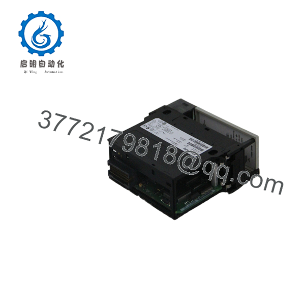
1756-DNB
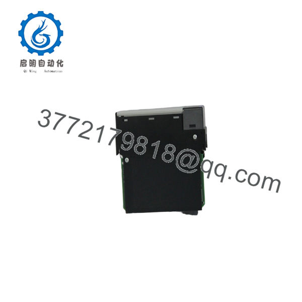
1756-DNB
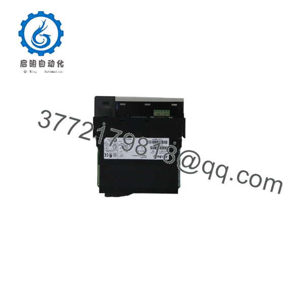
1756-DNB
Installation & Configuration Guide
Stage 1 – Pre-Installation Preparation (Estimated Time: 10 Minutes)
⚠️ Safety First
- Notify operations of the planned shutdown.
- Place the machine in a safe operating state.
- Apply lockout/tagout procedures.
- Remove power from the ControlLogix chassis.
- Wait at least 5 minutes before removing the module.
Tools Required
- Grounded ESD wrist strap
- PH1 screwdriver
- Fluke 115 digital multimeter
- Torque screwdriver
- Wire identification labels
- Smartphone for documenting DeviceNet wiring
Data Backup
- Upload the Studio 5000 project.
- Save the RSNetWorx for DeviceNet configuration.
- Record the DeviceNet node address.
- Record network baud rate.
- Photograph all DeviceNet connectors.
- Save the EDS file versions used on the network.
Stage 2 – Removing the Existing Module (Estimated Time: 10 Minutes)
- Verify chassis power is OFF.
- Disconnect the DeviceNet connector.
- Label the network cable.
- Release the module locking tabs.
- Remove the module using straight, even pressure.
- Inspect the backplane connector for bent pins or contamination.
⚠️ Keep the original module until the replacement completes network commissioning successfully.
Stage 3 – Installing the New Module (Estimated Time: 10 Minutes)
- Wear a grounded ESD wrist strap.
- Verify the replacement is 1756-DNB.
- Confirm firmware compatibility if required.
- Insert the module fully into the chassis.
- Tighten the DeviceNet connector to the specified torque.
- Reconnect the DeviceNet cable.
- Restore the original scanner configuration.
Self-Checklist
- Correct catalog number
- Module fully seated
- DeviceNet connector secured
- Node address verified
- Network baud rate confirmed
Stage 4 – Power-On & Testing (Estimated Time: 20 Minutes)
Pre-Power Checks
- Verify chassis power supply voltage.
- Measure DeviceNet network voltage (11–25 V DC).
- Confirm CAN_H and CAN_L wiring polarity.
- Check network termination resistors.
Commissioning Steps
- Energize the ControlLogix chassis.
- Observe the OK and NET status LEDs.
- Open Studio 5000.
- Verify the module is recognized.
- Open RSNetWorx for DeviceNet and verify all nodes are online.
- Test cyclic I/O and explicit messaging.
- Confirm all field devices respond correctly.
⚠️ Troubleshooting Notes
- NET LED flashing red: Check duplicate node addresses or incorrect baud rate.
- No DeviceNet communication: Measure network voltage and inspect CAN_H/CAN_L wiring.
- Devices missing: Verify EDS files, scan list configuration, and network termination.
Common Field Pitfalls
❗ Firmware Revision Differences
I’ve seen replacement modules installed with newer firmware while the project still referenced an older electronic key. Studio 5000 rejected the module even though the hardware was healthy. Record the original firmware revision before replacement.
❗ Scanner List Configuration
Installing the hardware alone is not enough. If the scan list is not restored, every DeviceNet device appears offline. Always save the RSNetWorx project before shutting down the system.
❗ DeviceNet Wiring Errors
One reversed CAN_H and CAN_L pair can disable the entire network. Verify every conductor before energizing the system. Never wire from memory.
❗ Network Power
The DeviceNet network requires its own external power supply. The 1756-DNB does not power field devices. Measure network voltage before troubleshooting communication faults.
❗ Electrostatic Discharge
Communication processors are particularly sensitive to static discharge. Handle the module only by its edges and always use a grounded ESD wrist strap.
Keep these checks in mind and you’ll eliminate most DeviceNet startup problems before production resumes.
Frequently Asked Questions (FAQ)
Q1. Is the Allen-Bradley 1756-DNB obsolete?
No.
The 1756-DNB remains an active Rockwell Automation product and continues to receive firmware, documentation, repair support, and a standard one-year warranty.
Q2. Can I hot-swap the 1756-DNB?
ControlLogix platforms support Removal and Insertion Under Power (RIUP) for many modules, but replacing a DeviceNet scanner on a live production network is generally discouraged. DeviceNet I/O communications stop during replacement, and network recovery may require scanner configuration verification.
Q3. What devices can communicate with the 1756-DNB?
The module communicates with DeviceNet-compatible equipment including:
- FLEX I/O
- POINT I/O
- ArmorBlock I/O
- PowerFlex drives
- Motor starters
- Valve manifolds
- Barcode readers
- Vision systems
- Other CIP-based DeviceNet devices
It supports up to 64 DeviceNet nodes on one network.
Q4. Does replacing the scanner erase my PLC program?
No.
The PLC application remains in the ControlLogix controller. However, the DeviceNet scan list and network configuration must match the original installation. Keep backups of both the Studio 5000 project and the RSNetWorx configuration.
Q5. Why is New Surplus inventory less expensive than OEM distribution?
Most New Surplus modules originate from canceled automation projects, unused maintenance inventory, or system upgrades. The lower selling price reflects inventory source rather than reduced capability. Verify serial numbers, inspection reports, firmware revision, and warranty before purchase.
Q6. How is each 1756-DNB inspected before shipment?
Each module should complete a documented inspection process:
- Inbound Inspection & Traceability
- Verify OEM labels and serial numbers.
- Inspect housing, connectors, and PCB condition.
- Check for corrosion, scratches, repairs, and UV discoloration.
- Functional Testing
- Install the module in a genuine ControlLogix chassis.
- Verify LED startup sequence.
- Establish DeviceNet communications.
- Test scanner operation with multiple DeviceNet devices.
- Perform continuous operation for more than 24 hours.
- Electrical Testing
- Insulation resistance test using a 500 V Megger.
- Ground continuity verification.
- Communication circuit inspection.
- Firmware Verification
- Record firmware revision.
- Verify hardware revision.
- Confirm DeviceNet communication speed.
- Final QC & Packaging
- QC inspector approval.
- Anti-static ESD packaging.
- Heavy-duty corrugated shipping carton.
- QC Passed label with inspection date.
Test photographs and communication test videos should be available upon request.
Q7. What should I verify before installing a replacement 1756-DNB?
Before commissioning, verify:
- Exact catalog number (1756-DNB)
- Firmware revision
- DeviceNet node address
- Network baud rate
- Scan list configuration
- CAN_H/CAN_L wiring
- DeviceNet power supply voltage
- Chassis power capacity
From practical commissioning experience, most DeviceNet failures originate from network configuration, duplicate node addresses, or wiring issues rather than a defective scanner module. Spending a few minutes documenting the original network usually prevents hours of troubleshooting later.



