
 WhatsApp: +86 16626708626
 Email:
  Phone: +86 16626708626
Description
Key Technical Specifications
| Parameter | Value |
|---|---|
| Product Type | High-Speed Counter Module |
| Manufacturer | Allen-Bradley / Rockwell Automation |
| Model Number | 1756-HSC |
| Product Series | ControlLogix |
| Counter Channels | 2 |
| Inputs per Counter | 3 (A, B, Z/Gate/Reset) |
| Digital Outputs | 4 (2 per counter) |
| Maximum Counting Frequency | 1 MHz |
| Maximum Encoder Frequency | 250 kHz (Quadrature X1/X4) |
| Maximum Rate Measurement | 500 kHz |
| Count Range | 0 to 16,777,214 |
| Input Voltage | 4.5–5.5 V DC or 10–26.4 V DC |
| Current Draw | 300 mA @ 5.1 V DC, 3 mA @ 24 V DC |
| Power Dissipation | 5.6 W |
| Isolation Voltage | 125 V continuous (input-to-backplane) |
| Operating Temperature | 0 to 60 °C |
| Storage Temperature | −40 to 85 °C |
| Relative Humidity | 5–95% non-condensing |
The 1756-HSC is an active ControlLogix specialty I/O module designed for high-speed counting, quadrature encoder feedback, rate measurement, and position monitoring in motion-related industrial applications.
Product Introduction
The Allen-Bradley 1756-HSC is a ControlLogix high-speed counter module used to acquire high-frequency pulse signals from encoders, proximity sensors, flow meters, and other pulse-generating devices. Unlike standard digital input modules, the 1756-HSC performs hardware-based counting independently of the PLC scan cycle, allowing reliable operation at input frequencies up to 1 MHz.
In production environments, this module is commonly installed for conveyor tracking, cut-to-length machines, web handling equipment, rotary indexing tables, packaging systems, and speed monitoring applications where deterministic pulse acquisition is required.
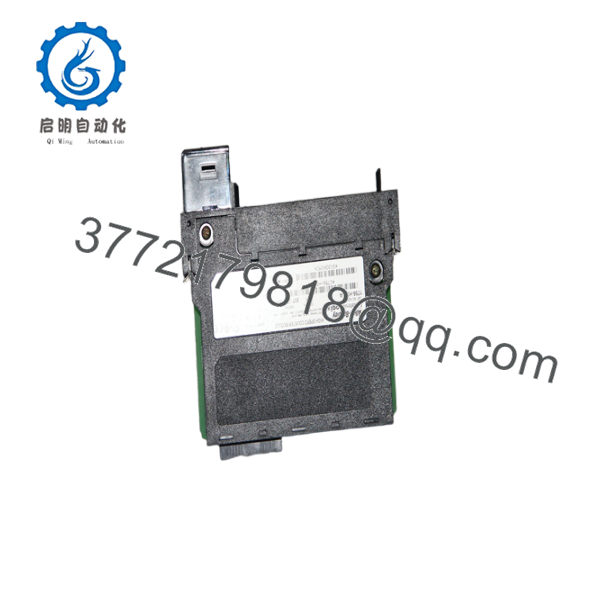
1756-HSC
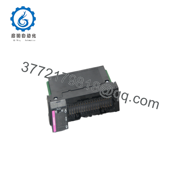
1756-HSC
Installation & Configuration Guide
Stage 1 – Pre-Installation Preparation (Estimated Time: 10 Minutes)
⚠️ Safety First
- Notify production personnel of scheduled downtime.
- Stop all machine motion.
- Apply lockout/tagout procedures.
- Remove ControlLogix chassis power.
- Wait at least 5 minutes before opening the enclosure.
Tools Required
- Grounded ESD wrist strap
- PH1 screwdriver
- Fluke 115 digital multimeter
- Torque screwdriver
- Wire identification labels
- Smartphone for wiring documentation
Data Backup
- Upload the Studio 5000 project.
- Record module configuration.
- Document encoder wiring.
- Photograph terminal connections.
- Save electronic keying settings.
- Record firmware revision.
Stage 2 – Removing the Existing Module (Estimated Time: 10 Minutes)
- Verify chassis power is OFF.
- Disconnect the removable terminal block.
- Label every encoder cable.
- Release the module locking tabs.
- Pull the module straight out.
- Inspect the chassis connector and terminal block.
⚠️ Keep the original module available until the replacement has completed commissioning.
Stage 3 – Installing the New Module (Estimated Time: 15 Minutes)
- Wear a grounded ESD wrist strap.
- Confirm the replacement catalog number is 1756-HSC.
- Install the module completely into the chassis.
- Reconnect the removable terminal block.
- Verify encoder A, B, and Z channel wiring.
- Restore the original module configuration.
- Verify electronic keying and firmware compatibility.
Self-Checklist
- Correct catalog number
- Module fully seated
- Encoder wiring verified
- Configuration restored
- Terminal block secured
Stage 4 – Power-On & Testing (Estimated Time: 20 Minutes)
Pre-Power Checks
- Measure supply voltage.
- Verify encoder supply voltage.
- Confirm cable shielding and grounding.
- Inspect encoder connector integrity.
Commissioning Steps
- Apply chassis power.
- Verify module OK LED.
- Open Studio 5000.
- Confirm module recognition.
- Monitor live counter values.
- Rotate the encoder manually.
- Verify count direction, rate measurement, and digital outputs.
⚠️ Troubleshooting Notes
- Module fault after startup: Verify firmware compatibility and electronic keying.
- Counter does not increment: Check encoder supply voltage and A/B signal wiring.
- Incorrect count direction: Reverse encoder A and B channels or update software configuration.
- Unstable counts: Inspect cable shielding and separate encoder wiring from VFD motor cables.
Common Field Pitfalls
❗ Firmware Revision Mismatch
A replacement module with a newer firmware revision may fail electronic keying. Record the original firmware before removing the module.
❗ Encoder Shield Grounding
This causes more commissioning delays than failed hardware. Route encoder cables separately from motor leads and terminate shields according to the installation manual. Poor grounding often produces intermittent counts whenever nearby VFDs accelerate. Field reports consistently identify electrical noise as a major source of erratic counter behavior.
❗ A/B Channel Wiring
Swapping A and B channels reverses the count direction. Before disconnecting the old module, photograph every terminal and verify the replacement matches exactly.
❗ Input Voltage Selection
The module accepts both 5 V and 12/24 V encoder inputs, but the encoder power supply must match the module configuration. Verify voltage before energizing the system.
❗ Electrostatic Discharge
The high-speed input circuitry is sensitive to static electricity. Handle the module only by its edges and install it on a grounded ESD work surface.
Keep these checks in mind and you’ll eliminate most high-speed counter commissioning problems before production resumes.
Frequently Asked Questions (FAQ)
Q1. Is the Allen-Bradley 1756-HSC obsolete?
No.
The 1756-HSC remains an active ControlLogix product supported by Rockwell Automation with firmware updates, repair services, and a standard one-year warranty.
Q2. What applications is the 1756-HSC designed for?
Typical applications include:
- Rotary encoder feedback
- Conveyor tracking
- Cut-to-length systems
- Flying shear control
- Packaging machinery
- Flow meter pulse counting
- Speed monitoring
- Position measurement
Its dedicated hardware counter allows accurate pulse acquisition without depending on controller scan time.
Q3. Can I use a standard digital input module instead of a 1756-HSC?
Generally, no.
Standard digital input modules rely on the PLC scan cycle and cannot reliably capture pulse frequencies approaching hundreds of kilohertz. The 1756-HSC is purpose-built for high-speed counting up to 1 MHz.
Q4. Does replacing the module erase my PLC program?
No.
The ControlLogix application remains stored in the controller. However, you should back up the module configuration, electronic keying settings, and encoder parameters before replacing the hardware.
Q5. Why is a New Surplus module less expensive than OEM distribution?
New Surplus inventory generally comes from canceled automation projects, spare parts inventories, or unused maintenance stock. Lower pricing reflects inventory source rather than reduced capability. Request the inspection report, hardware revision, firmware version, and warranty details before purchasing.
Q6. How is each 1756-HSC inspected before shipment?
Each module should complete a documented quality inspection:
- Inbound Inspection & Traceability
- Verify OEM serial numbers.
- Inspect housing, connectors, and terminal block.
- Check for corrosion, repair marks, scratches, and UV discoloration.
- Functional Testing
- Install the module in a genuine ControlLogix chassis.
- Verify LED startup sequence.
- Test quadrature encoder inputs.
- Verify counter outputs.
- Perform continuous operation for more than 24 hours under simulated load.
- Electrical Testing
- Perform insulation resistance testing using a 500 V Megger.
- Verify ground continuity.
- Inspect input isolation.
- Firmware Verification
- Record firmware revision.
- Verify electronic keying.
- Confirm hardware revision.
- Final QC & Packaging
- QC inspector approval.
- Anti-static ESD packaging.
- Heavy-duty corrugated shipping carton.
- QC Passed label with inspection date.
Test photographs and functional test videos should be available upon request.
Q7. What should I verify before installing a replacement 1756-HSC?
Before commissioning, verify:
- Exact catalog number (1756-HSC)
- Firmware revision
- Encoder voltage
- A/B/Z wiring
- Electronic keying
- Shield grounding
- Chassis power capacity
- Studio 5000 hardware configuration
From practical field experience, most high-speed counter faults originate from encoder wiring, electrical noise, or grounding issues—not from the module itself. Careful documentation of the original installation and proper cable routing usually prevent hours of unnecessary troubleshooting.



