
 WhatsApp: +86 16626708626
 Email:
  Phone: +86 16626708626
Description
Key Technical Specifications
| Parameter | Value |
|---|---|
| Product Type | Digital DC Input Module |
| Manufacturer | Allen-Bradley / Rockwell Automation |
| Model Number | 1756-IB16I |
| Product Series | ControlLogix |
| Number of Inputs | 16 individually isolated channels |
| Input Voltage | 10–30 V DC |
| Nominal Voltage | 24 V DC |
| Input Type | Sink/Source Compatible |
| Isolation Voltage | 250 V continuous (channel-to-channel and channel-to-backplane) |
| Input Filter | User selectable (0, 1, 2 ms ON; 0, 1, 2, 9, 18 ms OFF) |
| Cyclic Update Time | 200 μs to 750 ms |
| Current Draw | 100 mA @ 5.1 V DC; 3 mA @ 24 V DC |
| Power Dissipation | 5 W maximum |
| Operating Temperature | 0 to 60 °C |
| Storage Temperature | −40 to 85 °C |
| Relative Humidity | 5–95% non-condensing |
The 1756-IB16I is an active ControlLogix input module featuring 16 individually isolated digital inputs, making it suitable for applications where electrical isolation between field devices is required.
Product Introduction
The Allen-Bradley 1756-IB16I is a ControlLogix 16-point isolated digital input module designed to interface 10–30 V DC field signals with a ControlLogix controller. Individual channel isolation minimizes the effects of ground potential differences and electrical noise commonly found in industrial environments.
In field installations, this module is commonly used for limit switches, proximity sensors, pushbuttons, safety monitoring interfaces, auxiliary contacts, and distributed machine inputs where channel isolation improves system reliability and simplifies troubleshooting.
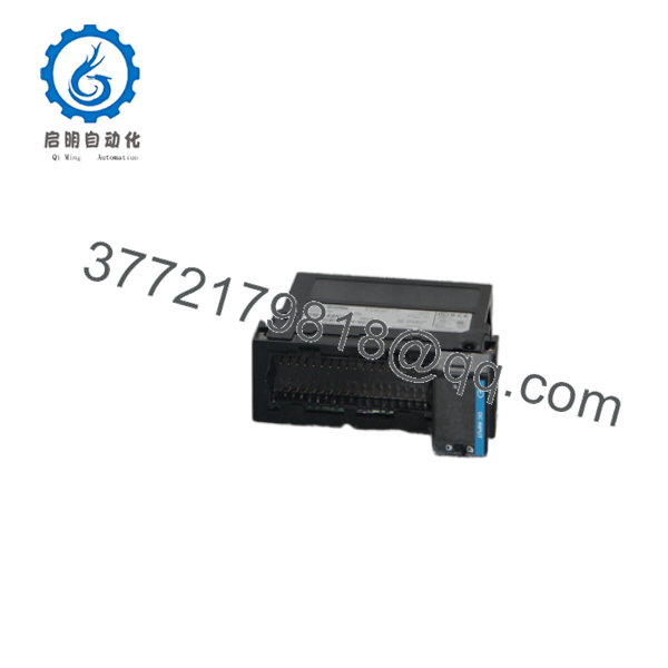
1756-IB16I
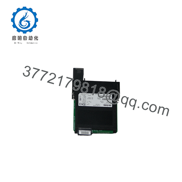
1756-IB16I
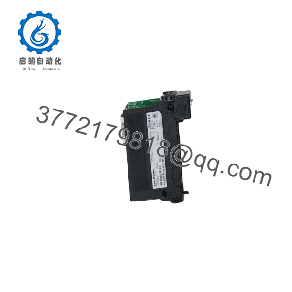
1756-IB16I
Installation & Configuration Guide
Stage 1 – Pre-Installation Preparation (Estimated Time: 10 Minutes)
⚠️ Safety First
- Notify production personnel of the planned shutdown.
- Bring the equipment to a safe operating condition.
- Apply lockout/tagout procedures.
- Remove power from the ControlLogix chassis.
- Wait at least 5 minutes for stored energy to discharge.
Tools Required
- Grounded ESD wrist strap
- PH1 screwdriver
- Fluke 115 digital multimeter
- Torque screwdriver
- Wire labels
- Smartphone for wiring documentation
Data Backup
- Upload the Studio 5000 project.
- Record module slot assignment.
- Photograph every field wiring connection.
- Record input filter settings.
- Verify electronic keying configuration.
Stage 2 – Removing the Old Module (Estimated Time: 10 Minutes)
- Confirm chassis power is OFF.
- Remove the removable terminal block (RTB).
- Label every field wire.
- Release the module locking tabs.
- Pull the module straight out without twisting.
- Inspect the backplane connector for contamination or bent pins.
⚠️ Keep the original module until the replacement has passed functional testing.
Stage 3 – Installing the New Module (Estimated Time: 15 Minutes)
- Wear a grounded ESD wrist strap.
- Verify the replacement catalog number is 1756-IB16I.
- Install the module firmly into the chassis.
- Reinstall the RTB.
- Restore all field wiring according to the photographs.
- Verify input filter configuration.
- Confirm electronic keying settings.
Self-Checklist
- Correct catalog number
- Module fully seated
- RTB fully latched
- Wiring verified
- Input filters configured
Stage 4 – Power-On & Testing (Estimated Time: 20 Minutes)
Pre-Power Checks
- Verify 24 V DC field power.
- Check for shorts using a multimeter.
- Confirm field common wiring.
- Verify terminal torque.
Commissioning Steps
- Energize the ControlLogix chassis.
- Verify the module OK indicator.
- Open Studio 5000.
- Confirm the module is recognized.
- Force or actuate each field input.
- Verify every input changes state correctly.
- Return the controller to normal operation.
⚠️ Troubleshooting Notes
- Module fault: Verify firmware compatibility and electronic keying.
- Single input not responding: Check field voltage, sensor wiring, and channel isolation.
- Multiple inputs inactive: Verify external 24 V DC supply and RTB installation.
- Unexpected input chatter: Adjust the configurable input filter instead of immediately replacing the module.
Common Field Pitfalls
❗ Firmware Revision Mismatch
I’ve seen replacement modules rejected because the controller was configured for Exact Match electronic keying. Record the firmware revision before removing the original module.
❗ Individually Isolated Inputs
Unlike standard shared-common input cards, every channel on the 1756-IB16I is electrically isolated. This changes field wiring practices. Do not assume commons can be tied together simply because they were on another module.
❗ Input Filter Settings
This is a common commissioning mistake. Very short pulse signals may never register if long OFF filters are configured. Match the filter time to the application instead of leaving factory defaults.
❗ Wiring Documentation
Take clear photographs before disconnecting anything. Even experienced technicians occasionally transpose channels during replacement, especially when several identical sensor cables enter the panel.
❗ Electrostatic Discharge
The input isolation circuitry can be damaged by improper handling. Always install the module on an ESD-safe work surface while wearing a grounded wrist strap.
Keep these checks in mind and you’ll avoid most digital input commissioning problems before production resumes.
Frequently Asked Questions (FAQ)
Q1. Is the Allen-Bradley 1756-IB16I still an active product?
Yes.
The remains an active ControlLogix I/O module supported by Rockwell Automation with firmware updates, documentation, certifications, and a standard one-year warranty.
Q2. What is the advantage of individually isolated inputs?
Each of the 16 channels has its own electrical isolation. This reduces problems caused by ground loops, differing field potentials, and electrical noise. It is especially useful when signals originate from equipment powered by different power supplies or located in separate machine sections.
Q3. Can I replace a standard 1756-IB16 with a 1756-?
Mechanically, both modules fit a standard ControlLogix chassis. However, they have different electrical characteristics and wiring requirements. Verify the project configuration, terminal wiring, and electronic keying before substitution. Simply matching the physical size is not sufficient.
Q4. Will replacing the module erase my PLC program?
No.
The controller stores the application program. Replacing the input module does not erase controller memory. However, always back up the Studio 5000 project and document module configuration before maintenance.
Q5. Why is a New Surplus module less expensive than buying directly from the OEM?
New Surplus inventory typically comes from canceled projects, unused maintenance stock, or excess inventory. Lower pricing reflects inventory sourcing rather than reduced functionality. Request the serial number, inspection report, firmware revision, and warranty details before purchase.
Q6. How is each 1756- inspected before shipment?
Each module should complete a documented quality inspection:
- Inbound Inspection & Traceability
- Verify OEM serial numbers.
- Inspect enclosure, PCB, and connectors.
- Check for corrosion, scratches, repairs, and UV discoloration.
- Functional Testing
- Install in a genuine ControlLogix chassis.
- Verify LED startup sequence.
- Test all 16 isolated inputs using simulated field signals.
- Run continuously for more than 24 hours while monitoring channel status.
- Electrical Testing
- Perform insulation resistance testing using a 500 V Megger.
- Verify isolation between channels.
- Check ground continuity.
- Firmware & Configuration Verification
- Record firmware revision.
- Verify electronic keying compatibility.
- Final QC & Packaging
- QC approval.
- Anti-static ESD packaging.
- Heavy-duty corrugated carton.
- QC Passed label with inspection date.
Test reports, photographs, and functional test videos should be available upon request.
Q7. What should I verify before installing a replacement 1756-?
Before commissioning, verify:
- Exact catalog number ()
- Firmware revision
- Electronic keying settings
- Field supply voltage
- RTB installation
- Input filter configuration
- Chassis power capacity
- Studio 5000 hardware configuration
From practical field experience, most digital input problems are caused by wiring errors, incorrect field voltage, or configuration mismatches—not by a failed input module. Taking time to document the original installation typically prevents hours of unnecessary troubleshooting. Community experience also shows that firmware revisions and electronic keying settings can affect module replacement compatibility in some systems.



