
 WhatsApp: +86 16626708626
 Email:
  Phone: +86 16626708626
Description
Key Technical Specifications
| Parameter | Value |
|---|---|
| Product Type | Isolated Analog Input Module |
| Manufacturer | Allen-Bradley / Rockwell Automation |
| Model Number | 1756-IF6I |
| Product Series | ControlLogix |
| Number of Input Channels | 6 individually isolated |
| Supported Input Signals | ±10 V, 0–10.5 V, 0–5.25 V, 0–21 mA |
| Resolution | 16-bit |
| Conversion Method | Sigma-Delta A/D |
| Accuracy | Better than ±0.1% of range at 25 °C |
| Channel Isolation | 250 V continuous (channel-to-channel and channel-to-backplane) |
| Input Scan Time | 10 ms (Integer), 25 ms (Floating Point) minimum |
| Current Draw | 250 mA @ 5.1 V DC; 100 mA @ 24 V DC |
| Power Dissipation | 3.7 W (Voltage Mode), 4.3 W (Current Mode) |
| Common Mode Noise Rejection | 120 dB @ 60 Hz |
| Operating Temperature | 0 to 60 °C |
| Storage Temperature | −40 to 85 °C |
The 1756-IF6I is a six-channel, individually isolated analog input module that accepts both voltage and current signals. Each channel is independently isolated to reduce ground-loop issues and electrical noise in distributed process systems.
Product Introduction
The Allen-Bradley 1756-IF6I is a ControlLogix isolated analog input module designed for process measurements requiring high electrical isolation and measurement stability. It accepts common industrial analog signals including 0–20 mA, 4–20 mA, 0–10 V, and ±10 V, making it suitable for transmitters, analyzers, pressure instruments, flow meters, and level sensors.
Unlike standard shared-common analog cards, each input channel is electrically isolated. In field installations with long cable runs or multiple instrument power supplies, this isolation often eliminates nuisance measurement offsets caused by ground potential differences.
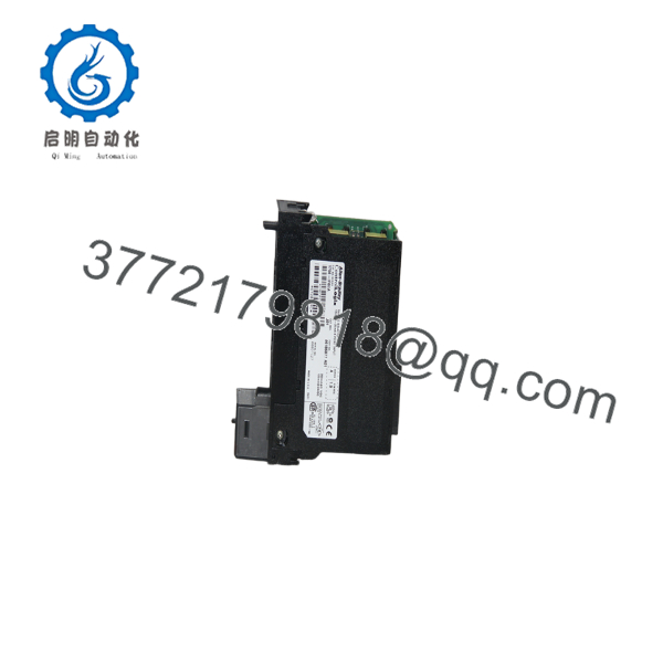
1756-IF6I
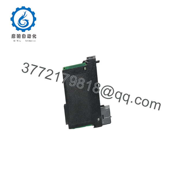
1756-IF6I
Installation & Configuration Guide
Stage 1 – Pre-Installation Preparation (Estimated Time: 10 Minutes)
⚠️ Safety First
- Notify operations before shutting down the process.
- Bring the equipment to a safe operating condition.
- Apply lockout/tagout procedures.
- Remove ControlLogix chassis power.
- Wait at least 5 minutes for internal capacitors to discharge.
Tools Required
- Grounded ESD wrist strap
- PH1 screwdriver
- Fluke 115 digital multimeter
- Precision loop calibrator (4–20 mA)
- Wire identification labels
- Smartphone for wiring documentation
Data Backup
- Upload the Studio 5000 project.
- Record all channel configurations.
- Photograph every terminal connection.
- Document voltage/current selections.
- Record firmware revision and electronic keying.
Stage 2 – Removing the Old Module (Estimated Time: 10 Minutes)
- Verify chassis power is OFF.
- Remove the removable terminal block (RTB).
- Label every field cable.
- Release the module locking tabs.
- Remove the module using straight, even pressure.
- Inspect the backplane connector for bent pins or contamination.
⚠️ Keep the original module until the replacement has completed calibration checks successfully.
Stage 3 – Installing the New Module (Estimated Time: 15 Minutes)
- Wear a grounded ESD wrist strap.
- Verify the replacement catalog number is 1756-IF6I.
- Install the module fully into the chassis.
- Reinstall the RTB.
- Restore all field wiring exactly as documented.
- Configure each channel for the correct voltage or current range.
- Verify electronic keying and firmware compatibility.
Self-Checklist
- Correct catalog number
- Module fully seated
- RTB secured
- Channel configuration verified
- Wiring confirmed
Stage 4 – Power-On & Testing (Estimated Time: 20 Minutes)
Pre-Power Checks
- Verify 24 V instrument power.
- Check loop polarity.
- Measure analog signal levels.
- Confirm shield grounding at one end only.
Commissioning Steps
- Apply chassis power.
- Verify the Module Health LED.
- Open Studio 5000.
- Confirm module recognition.
- Verify each analog channel with a calibrated signal source.
- Compare measured values with field instruments.
- Return the controller to RUN mode.
⚠️ Troubleshooting Notes
- Module fault: Verify firmware revision and electronic keying.
- Unstable readings: Inspect shield grounding and separate analog wiring from VFD motor cables.
- One channel offset: Verify field transmitter calibration and channel configuration before replacing the module.
- All channels incorrect: Check RTB wiring and external instrument power supply.
Common Field Pitfalls
❗ Firmware Revision Mismatch
If the controller uses Exact Match electronic keying, a firmware mismatch can prevent the module from establishing communication. Record the original firmware revision before replacement.
❗ Current vs. Voltage Configuration
I’ve seen technicians connect a 4–20 mA transmitter to a channel configured for voltage input. The result looked like a failed module, but the problem was simply incorrect channel configuration.
❗ Shield Grounding
Ground the cable shield at one end only. Connecting both ends often creates ground loops that introduce unstable analog readings. This issue becomes much more noticeable near variable frequency drives.
❗ Individually Isolated Channels
Every input channel has independent isolation. Don’t assume common returns can be tied together as they often are on shared-common analog modules.
❗ Electrostatic Discharge
The analog front-end circuitry is highly sensitive to static discharge. Handle the module only by its edges and install it on an ESD-safe work surface.
Keep these checks in mind and you’ll save yourself most analog commissioning headaches before startup.
Frequently Asked Questions (FAQ)
Q1. What types of analog signals does the 1756-IF6I support?
The module supports:
- ±10 V
- 0–10.5 V
- 0–5.25 V
- 0–21 mA (including standard 4–20 mA applications)
Each channel is independently configurable through Studio 5000.
Q2. Why choose the 1756-IF6I instead of a standard analog input module?
The primary advantage is individual channel isolation. Each of the six inputs is electrically isolated from every other channel and from the backplane. This greatly reduces measurement errors caused by ground loops and electrical interference in large industrial facilities.
Q3. Can I mix voltage and current inputs on the same module?
Yes.
Each channel can be configured independently for its required input type. One channel may measure 4–20 mA, while another simultaneously measures 0–10 V, provided each channel is configured correctly.
Q4. Will replacing the module erase my PLC program?
No.
The ControlLogix controller stores the application program. Replacing the analog input module does not affect controller memory. However, always back up the project and document channel configurations before maintenance.
Q5. Why is a New Surplus module less expensive than OEM distribution?
New Surplus inventory typically comes from canceled projects, unused maintenance inventory, or plant upgrades. Lower pricing reflects inventory sourcing rather than product quality. Request inspection records, firmware information, serial number verification, and warranty details before purchasing.
Q6. How is every 1756- inspected before shipment?
Each module should complete a documented quality inspection:
- Inbound Inspection & Traceability
- Verify OEM labels and serial numbers.
- Inspect enclosure, connectors, and PCB.
- Check for corrosion, repair marks, scratches, and UV discoloration.
- Functional Testing
- Install in a genuine ControlLogix chassis.
- Verify startup diagnostics.
- Test all six channels using calibrated voltage and current sources.
- Perform continuous operation for more than 24 hours while monitoring stability.
- Electrical Testing
- Perform insulation resistance testing using a 500 V Megger.
- Verify channel-to-channel isolation.
- Check grounding continuity.
- Firmware & Configuration Verification
- Record firmware revision.
- Verify electronic keying compatibility.
- Confirm channel configuration functions correctly.
- Final QC & Packaging
- QC inspector approval.
- Anti-static ESD packaging.
- Heavy-duty corrugated carton.
- QC Passed label with inspection date.
Test reports, calibration data, photographs, and functional test videos should be available upon request.
Q7. What should I verify before installing a replacement 1756-?
Before commissioning, verify:
- Exact catalog number ()
- Firmware revision
- Voltage/current channel configuration
- Instrument loop power
- RTB wiring
- Electronic keying
- Shield grounding
- Chassis power capacity
In practical commissioning work, most analog input problems are caused by configuration errors, transmitter wiring, or grounding issues rather than a defective analog module. Spending a few extra minutes documenting the original installation usually saves hours of troubleshooting after startup.



