
 WhatsApp: +86 16626708626
 Email:
  Phone: +86 16626708626
Description
3. Key Technical Specifications
| Parameter | Specification Value |
|---|---|
| Catalog Part Number | 1756-IF8 |
| Manufacturer | Allen-Bradley (Rockwell Automation) |
| Compatible Architecture | Allen-Bradley ControlLogix (1756 Chassis System) |
| Number of Inputs | 8 single-ended, 4 differential, or 2 high-speed differential |
| Input Signal Ranges | ±10V, 0 to 10V, 0 to 5V, 0 to 20 mA (software configurable) |
| Resolution | 16 bits across 21 mA (0.32 µA/bit), 16 bits across 10.5V (150 µV/bit) |
| Backplane Current Draw | 150 mA @ 5.1V DC, 120 mA @ 24V DC (Total power ~3.64 W) |
| Module Isolation | 250V continuous isolation (Group-to-Backplane); non-channel-isolated |
| Conversion Method | Delta-Sigma analog-to-digital conversion |
| Data Format | IEEE 32-bit floating point or 16-bit integer formats |
| Compatible Terminal Block | 1756-TBCH (36-pin cage clamp) or 1756-TBNH (36-pin NEMA spring clamp) |
4. Product Introduction & Supply Chain Strategy
The Allen-Bradley 1756-IF8 is an 8-channel non-isolated analog input card built for ControlLogix controller chassis. Capable of receiving voltage or current signals from pressure transmitters, flow meters, and temperature sensors, it provides high-resolution analog conversion directly to the controller backplane without requiring external transmitters.
This product is a Brand New Surplus unit. It is not used, not pulled from a decommissioned plant, and not refurbished. All modules undergo rigorous quality verification to ensure OEM-level reliability.
Securing the 1756-IF8 as New Surplus provides key operational stability. Refurbished analog input cards carry hidden risks, such as drift in calibration resistors, signal cross-talk from aged filtering capacitors, or physical pin wear on the backplane connector. Purchasing verified New Surplus eliminates these failure modes while bypassing OEM factory lead times.
5. Installation & Configuration Guide
Stage 1: Pre-Installation (Prep & Safety)
- Open the main incoming AC power breaker feeding the ControlLogix chassis and apply Lock-Out/Tag-Out (LOTO).
- Put on a grounded ESD wrist strap before opening the cabinet or touching module circuit boards.
- Verify that current loop sense resistors are installed across inputs if configuring channels for 0–20 mA current mode.
- Label field wiring leads matching the pinout of the 36-pin removable terminal block (1756-TBCH or 1756-TBNH).
Stage 2: Removal
- Unlatch the door on the 36-pin Removable Terminal Block (RTB) and loosen the top and bottom RTB retaining screws to pull the RTB away from the module.
- Depress the top and bottom module locking tabs on the 1756-IF8 chassis card.
- Slide the module straight out along the chassis guide rails to avoid bending backplane pins.
- Place the removed card into an ESD protective bag.
Stage 3: Installation (Clone & Seat)
- Align the 1756-IF8 circuit board with the guide slots of the designated chassis slot.
- Push the module firmly into the slot until the top and bottom retention tabs snap locked into the chassis frame.
- Reattach the pre-wired 36-pin RTB onto the front of the module and tighten the top/bottom RTB holding screws.
Stage 4: Power-On & Testing
- Restore power to the 1756 chassis power supply.
- Check module status LEDs:
OKshould show solid green. - Open Studio 5000 Logix Designer, verify slot status, and configure channel input ranges, digital filtering, and scaling parameters in the Module Properties wizard.
- Use a calibrated signal generator (4–20 mA or 0–10V) to test signal accuracy across each channel.
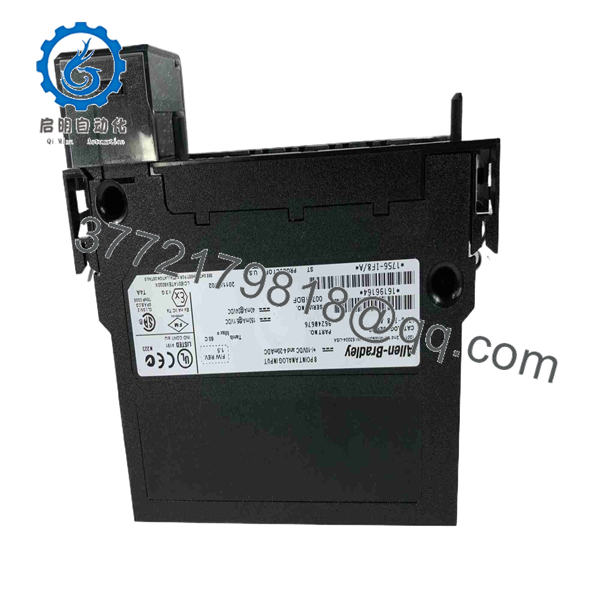
1756-IF8
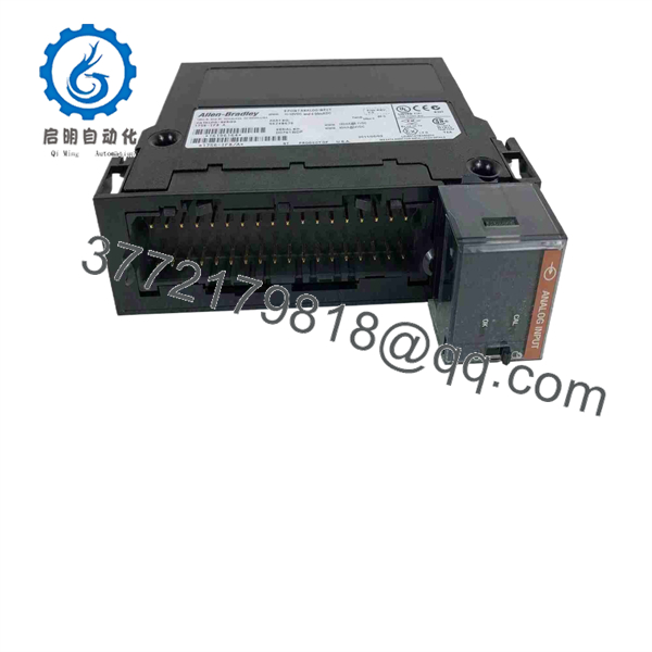
1756-IF8
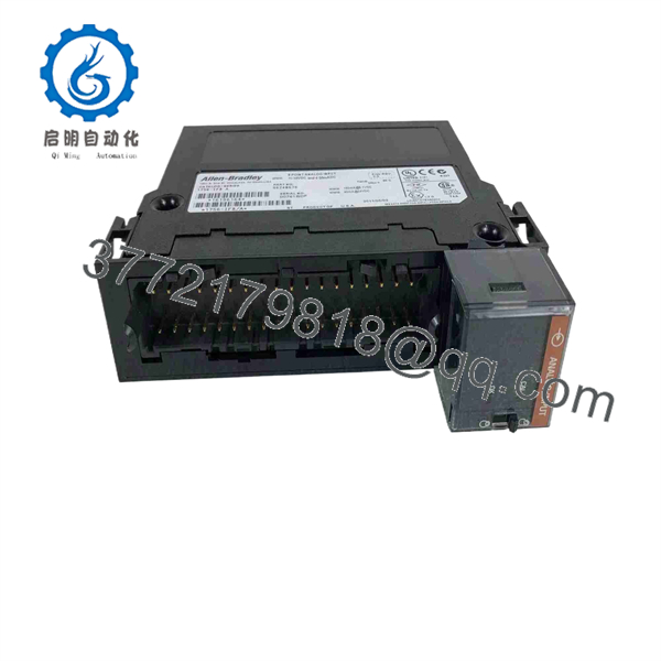
1756-IF8
6. Firmware/Software Versions & Upgrade Notes
The 1756-IF8 is fully integrated into Studio 5000 Logix Designer and RSLogix 5000 environment.
- Software Support: Native Module Profiles supported across all versions of Studio 5000 / RSLogix 5000.
- Wiring Choice: For 4–20 mA current operation, current sense resistors are built into or wired across the 1756-TBCH terminal block. Ensure correct wiring polarity.
- Isolated Alternative: If your application experiences heavy ground loop noise between field instruments, consider using the channel-isolated 1756-IF8I or 1756-IF16 modules instead.
7. Frequently Asked Questions (FAQ)
Q: Is this 1756-IF8 module brand new or has it been pulled from a decommissioned plant?
A: This product is a Brand New Surplus unit. It is not used, not pulled from a decommissioned plant, and not refurbished. All modules undergo rigorous quality verification to ensure OEM-level reliability.
Q: What is the difference between 1756-IF8 and 1756-IF8I?
A: The 1756-IF8 features non-isolated channels (group isolated from backplane), whereas the 1756-IF8I provides individual channel-to-channel isolation for environments with severe ground potential differences.
Q: Does the 1756-IF8 come with the removable terminal block (RTB)?
A: Removable Terminal Blocks (1756-TBCH or 1756-TBNH) are sold separately by Rockwell Automation. However, if you are replacing an existing card, your current RTB clips directly onto the new card.
Q: Can I mix voltage and current signals on the same 1756-IF8 module?
A: Yes. Each channel on the 1756-IF8 is individually configurable in Studio 5000 for either voltage (e.g., 0–10V) or current (e.g., 4–20 mA) operation.
Q: What warranty applies to this New Surplus module?
A: We back this module with a full 1-year functional replacement warranty from the date of shipment, ensuring zero operational risk.



