
 WhatsApp: +86 16626708626
 Email:
  Phone: +86 16626708626
Description
Key Technical Specifications
| Parameter | Specification Value |
|---|---|
| Catalog Number | 1756-L55M13 (Consists of 1756-L55 CPU + 1756-M13 Memory Expansion Daughtercard) |
| User Data & Logic Memory | 1.5 MB |
| Processor Family | Logix5555 |
| Serial Communication Port | 1x RS-232 (DF1 Full-Duplex, DF1 Radio Modem, DH-485, ASCII) |
| Maximum Digital I/O | 128,000 inputs/outputs total |
| Maximum Analog I/O | 4,000 inputs/outputs total |
| Maximum Controller Tasks | 32 tasks (1 continuous task + up to 31 periodic/event tasks) |
| Backplane Current (5.1V DC) | 1.25 A |
| Backplane Current (24V DC) | 14 mA |
| Power Dissipation | 5.7 W max |
| Battery Backed Memory | Requires 1756-BA1, 1756-BA2, or 1756-BATM battery module |
Product Introduction & Supply Chain Strategy
This product is a Brand New Surplus unit. It is not used, not pulled from a decommissioned plant, and not refurbished. All modules undergo rigorous quality verification to ensure OEM-level reliability. The Allen-Bradley 1756-L55M13 is a Logix5555 series controller bundling the core 1756-L55 processor with a 1.5 MB 1756-M13 memory expansion module. It handles high-speed discrete logic, analog process loops, motion coordination, and multi-network routing across ControlLogix backplanes.
With Rockwell Automation having officially discontinued the Logix5555 series, migrating to modern controllers like the 1756-L7x or 1756-L8x involves significant operational friction: rewiring, replacing backplane chassis, rewriting RSLogix 5000 code, and undergoing lengthy re-validation processes. Procuring a factory-fresh surplus 1756-L55M13 delivers an immediate 1:1 drop-in replacement. It restores full system operation with zero software modifications, maintaining your existing control architecture while avoiding major capital expenditure outlays.
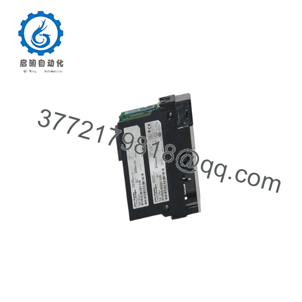
1756-L55M13
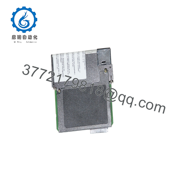
1756-L55M13
Installation & Configuration Guide
1
Stage 1: Pre-Installation (Prep & Safety)
Perform software backup, isolate rack power, and attach ESD wrist strap
1.Stage 1: Pre-Installation (Prep & Safety):Perform software backup, isolate rack power, and attach ESD wrist strap.
- Ensure a complete project backup (
.ACDfile) is saved from RSLogix 5000 via serial or network bridge connection before servicing. - Execute strict Lock-Out/Tag-Out (LOTO) procedures on the ControlLogix chassis power supply.
- Wear a grounded Electrostatic Discharge (ESD) wrist strap attached to unpainted enclosure steel.
- Verify that the internal 1756-M13 memory card and fresh battery (1756-BA1/BA2) are securely installed on the CPU daughterboard.
2
Stage 2: Removal
Disconnect serial line, switch to PROG mode, and pull processor out
2.Stage 2: Removal:Disconnect serial line, switch to PROG mode, and pull processor out.
- Turn the keyswitch on the front panel to the
PROGposition. - Disconnect any 1756-CP3 RS-232 serial programming cable from the front port.
- Depress the upper and lower module retention tabs on the 1756-L55M13 housing.
- Slide the controller straight out of the chassis slot to prevent backplane pin damage.
3
Stage 3: Installation (Clone & Seat)
Align guide rails, lock controller into slot, and re-attach serial cable
3.Stage 3: Installation (Clone & Seat):Align guide rails, lock controller into slot, and re-attach serial cable.
- Align the top and bottom circuit board edges of the new 1756-L55M13 with the chassis card guides.
- Push the controller firmly into the chassis slot until both top and bottom latches click into place.
- Re-connect the RS-232 serial cable or ensure network bridge cards (EtherNet/IP, ControlNet) are online in adjacent slots.
4
Stage 4: Power-On & Testing
Apply power, observe LED diagnostics, and download project file
4.Stage 4: Power-On & Testing:Apply power, observe LED diagnostics, and download project file.
- Re-apply power to the ControlLogix chassis power supply.
- Monitor the front status LEDs: verify
RUNis OFF,FORCEis OFF,BATis OFF (indicating healthy battery), andOKturns solid GREEN after self-test. - Connect via RSLogix 5000 (v10 through v16), match the firmware revision, and download the project file to the controller.
- Turn the physical keyswitch from
PROGtoREMorRUNand confirm that all I/O connections transition to healthy status.
Firmware/Software Versions & Upgrade Notes
- Software Compatibility: Programmed exclusively using RSLogix 5000 (typically supported from Version 10 up to Version 16). The Logix5555 platform cannot be programmed using Studio 5000 (v21+).
- Firmware Flashing: Firmware revisions (e.g., v13, v15, v16) are flashed onto the processor using ControlFLASH via the front RS-232 port or across the backplane through a 1756-ENBT or 1756-CNBR bridge card. Ensure the physical firmware on the 1756- matches the major/minor revision saved in your
.ACDproject file. - Memory Architecture: The 1756-L55 processor utilizes plug-in memory daughtercards. The 1756- includes a 1.5 MB volatile SRAM card (
1756-M13). If non-volatile memory backup is required to protect programs against prolonged battery discharge, a 1756-M16 non-volatile memory module can be added.
Frequently Asked Questions (FAQ)
What is the exact difference between a 1756-L55, 1756-, and 1756-L61?
- 1756-L55: The base Logix5555 processor unit without a memory daughtercard.
- The 1756-L55 processor pre-assembled with a 1.5 MB 1756-M13 SRAM memory card.
- 1756-L61: A newer generation Logix5561 (ControlLogix 5560 series) processor featuring 2 MB built-in onboard memory without requiring separate daughtercards.
Can I upgrade a 1756- to a higher memory capacity without replacing the CPU?
Yes. You can swap the 1.5 MB 1756-M13 daughtercard for a higher capacity card such as the 1756-M14 (3.5 MB) or 1756-M15 (7.5 MB) while keeping the same 1756-L55 base unit.
Why is the BAT LED red on my 1756- controller?
A solid red BAT LED indicates that the backup battery (1756-BA1 or 1756-BA2) voltage has dropped below the critical threshold. If power is lost to the chassis while the BAT LED is red, the program stored in volatile RAM will be lost. Replace the battery immediately while chassis power is turned ON to preserve the memory contents.
What causes a “Non-Recoverable Major Fault” on this processor?
A solid red OK LED indicates a severe hardware or memory error. This can be caused by static discharge (ESD), internal memory corruption, or complete battery loss during power removal. Attempt to clear the fault by cycling power or downloading the project via RSLogix 5000; if the solid red OK light persists, the processor requires replacement.
What warranty coverage is included with this New Surplus controller?
We back this unit with a comprehensive 1-Year hardware replacement warranty (depending on your service agreement tier). In the event of any hardware fault during standard operation, an immediate replacement unit is dispatched directly from our buffer stock.



