
 WhatsApp: +86 16626708626
 Email:
  Phone: +86 16626708626
Description
Key Technical Specifications
| Parameter | Value |
|---|---|
| Product Type | GuardLogix Safety Controller |
| Manufacturer | Allen-Bradley / Rockwell Automation |
| Model Number | 1756-L72S |
| Product Series | GuardLogix 5570 |
| Standard User Memory | 4 MB |
| Safety Memory | 2 MB |
| I/O Memory | 0.98 MB |
| Maximum Digital I/O | 128,000 points |
| Maximum Analog I/O | 4,000 points |
| Programming Software | Studio 5000 Logix Designer |
| Programming Port | USB 2.0 |
| Nonvolatile Memory | 1 GB Secure Digital (1756-SD1 supplied) |
| Energy Storage Module | 1756-ESMCAP (factory installed) |
| Backplane Current | 800 mA @ 5.1 V DC; 5 mA @ 1.2 V DC |
| Power Dissipation | 2.5 W |
| Isolation Voltage | 30 V continuous (USB-to-system) |
| Operating Temperature | 0 to 60 °C |
| Storage Temperature | −40 to 85 °C |
The 1756-L72S is a GuardLogix 5570 safety controller that combines standard ControlLogix processing with integrated safety control. It provides 4 MB of standard memory, 2 MB of dedicated safety memory, supports up to 128,000 digital I/O points, and ships with a 1 GB SD card and removable energy storage module.
Product Introduction
The Allen-Bradley 1756-L72S is a GuardLogix safety controller designed for machine and process applications that require both standard automation and functional safety within a single ControlLogix platform. It executes standard logic alongside TÜV-certified safety logic while supporting distributed I/O, motion, and industrial network communications through compatible ControlLogix communication modules.
The controller is commonly installed in packaging, automotive assembly, material handling, and process industries where safety interlocks, emergency stop circuits, and standard machine control must operate together. For applications targeting SIL 3 (IEC 61508) or PLe (ISO 13849), the GuardLogix architecture simplifies project management by keeping both standard and safety tasks within one engineering environment.
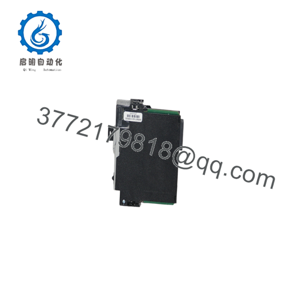
1756-L72S
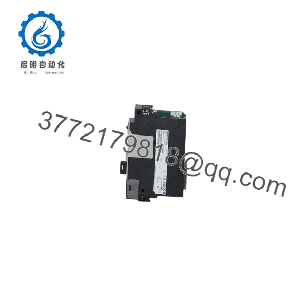
1756-L72S
Installation & Configuration Guide
Stage 1 – Pre-Installation Preparation (Estimated Time: 15 Minutes)
⚠️ Safety First
- Notify operations and maintenance personnel.
- Bring the machine to a verified safe state.
- Apply lockout/tagout procedures.
- Remove power from the ControlLogix chassis.
- Wait at least 5 minutes before servicing.
Tools Required
- Grounded ESD wrist strap
- PH1 screwdriver
- Fluke 115 digital multimeter
- Laptop with Studio 5000 Logix Designer
- USB programming cable
- Smartphone for documentation
Data Backup
- Upload the complete Studio 5000 project.
- Record controller firmware revision.
- Backup the Safety Signature.
- Save network parameters.
- Record Safety Network Number (SNN).
- Backup the SD card if used.
Stage 2 – Removing the Existing Controller (Estimated Time: 10 Minutes)
- Verify chassis power is OFF.
- Disconnect the USB cable.
- Remove the SD card if necessary.
- Label all communication modules.
- Release the locking tabs.
- Pull the controller straight out.
- Inspect the backplane connector.
⚠️ Do not discard the original controller until the replacement has completed functional and safety validation.
Stage 3 – Installing the New Controller (Estimated Time: 20 Minutes)
- Wear a grounded ESD wrist strap.
- Confirm the replacement catalog number is 1756-L72S.
- Verify the Energy Storage Module is installed.
- Insert the controller completely into the chassis.
- Install the SD card if required.
- Connect the USB programming cable.
- Verify firmware compatibility before downloading the project.
Self-Checklist
- Correct controller installed
- Energy Storage Module present
- SD card verified
- Firmware matches project
- Safety Signature documented
Stage 4 – Power-On & Testing (Estimated Time: 30 Minutes)
Pre-Power Checks
- Verify chassis power supply.
- Inspect the Energy Storage Module.
- Confirm communication module status.
- Verify grounding.
Commissioning Steps
- Energize the chassis.
- Observe the OK, RUN, and SAFETY LEDs.
- Connect using Studio 5000.
- Verify firmware revision.
- Confirm Safety Signature.
- Validate Safety Network Number (SNN).
- Perform complete safety validation before returning equipment to production.
⚠️ Troubleshooting Notes
- Safety Task Locked: Verify the Safety Signature and project revision.
- Major Fault: Confirm firmware compatibility before downloading the project.
- Safety I/O Offline: Verify the Safety Network Number and communication module configuration.
- Controller Rejects Download: Check controller revision and Studio 5000 software version compatibility.
Common Field Pitfalls
❗ Firmware Revision Mismatch
I’ve seen safety commissioning delayed because the replacement controller shipped with a different firmware revision. Record the original firmware before removing the controller. Safety projects generally require an exact firmware match unless the project has been upgraded.
❗ Safety Signature Changes
Every modification to validated safety logic generates a new Safety Signature. If this isn’t documented before replacement, acceptance testing becomes much more difficult.
❗ Safety Network Number (SNN)
The replacement controller must use the correct SNN. An incorrect Safety Network Number prevents Guard I/O devices from establishing safety communications even though standard Ethernet communication appears normal.
❗ Energy Storage Module
Unlike older battery-backed controllers, the 1756-L72S uses a removable capacitor-based Energy Storage Module. Verify its health during preventive maintenance because it protects controller data during power loss.
❗ Electrostatic Discharge
Safety controllers contain high-density electronics that are susceptible to ESD damage. Always use a grounded wrist strap and ESD-safe work surface.
Keep these checks in mind and you’ll avoid most GuardLogix commissioning delays before production resumes.
Frequently Asked Questions (FAQ)
Q1. Is the 1756-L72S a standard ControlLogix controller?
No.
The is a GuardLogix safety controller. It executes both standard control logic and certified safety logic within the same controller architecture while maintaining separate standard and safety memory areas.
Q2. What safety standards does the 1756- support?
When properly designed and validated, the controller supports applications targeting IEC 61508 SIL 3 and ISO 13849 Performance Level e (PLe). Overall compliance depends on the complete safety system design, field devices, and application validation—not the controller alone.
Q3. Can I replace a standard 1756-L72 with a 1756-?
Not as a direct hardware substitution.
Although both controllers share the same hardware platform, the GuardLogix controller introduces safety functions, Safety Signatures, Safety Network Numbers, and certified safety tasks. Migration requires project validation rather than simply swapping hardware.
Q4. Will replacing the controller erase my application?
Not if proper backups are available.
Before replacement, upload the complete Studio 5000 project, record the firmware revision, document the Safety Signature, and back up any data stored on the SD card.
Q5. Why is New Surplus inventory less expensive than buying directly from Rockwell Automation?
New Surplus controllers typically originate from canceled automation projects, OEM spare inventories, or unused maintenance stock. Lower pricing reflects inventory sourcing rather than reduced functionality. Always request the controller serial number, firmware revision, inspection report, and warranty documentation before purchase.
Q6. How is every 1756- inspected before shipment?
Each controller should complete a documented inspection procedure:
- Inbound Inspection & Traceability
- Verify OEM labels and serial numbers.
- Inspect enclosure, connectors, USB port, and PCB.
- Check for corrosion, repair marks, scratches, and UV discoloration.
- Functional Testing
- Install in a genuine GuardLogix chassis.
- Verify startup diagnostics.
- Test USB communications.
- Validate standard and safety task execution.
- Perform continuous operation for more than 24 hours while monitoring controller status.
- Electrical Testing
- Verify insulation resistance where applicable.
- Check ground continuity.
- Measure controller power consumption.
- Firmware & Configuration Verification
- Record firmware revision.
- Verify SD card functionality.
- Inspect the Energy Storage Module.
- Confirm Safety Signature generation.
- Final QC & Packaging
- QC inspector approval.
- Anti-static ESD packaging.
- Heavy-duty corrugated shipping carton.
- QC Passed label with inspection date.
Test reports, startup photographs, and functional test videos should be available upon request.
Q7. What should I verify before installing a replacement 1756-?
Before commissioning, verify:
- Exact catalog number ()
- Firmware revision
- Studio 5000 software compatibility
- Safety Signature
- Safety Network Number (SNN)
- SD card contents
- Energy Storage Module condition
- Chassis power capacity
From practical field experience, most GuardLogix replacement delays are caused by firmware mismatches, incorrect Safety Network Numbers, or undocumented Safety Signatures—not by defective controller hardware. Recording these values before removing the original controller typically prevents hours of recommissioning work.



