
 WhatsApp: +86 16626708626
 Email:
  Phone: +86 16626708626
Description
Key Technical Specifications
| Parameter | Value |
|---|---|
| Product Type | ControlLogix Processor Module |
| Manufacturer | Allen-Bradley / Rockwell Automation |
| Model Number | 1756-L75 |
| Product Series | ControlLogix 5570 |
| User Memory | 32 MB |
| I/O Memory | 0.98 MB |
| Nonvolatile Storage | 1 GB Secure Digital (1784-SD1, factory installed) |
| Programming Software | Studio 5000 Logix Designer |
| Programming Port | One USB 2.0 |
| Maximum Digital I/O | 128,000 points |
| Maximum Analog I/O | 4,000 points |
| Motion Axis Support | Up to 100 axes |
| Energy Storage Module | 1756-ESMCAP (factory installed) |
| Backplane Current | 800 mA @ 5.1 V DC; 5 mA @ 1.2 V DC |
| Power Dissipation | 2.5 W |
| Isolation Voltage | 30 V continuous (USB-to-system) |
| Operating Temperature | 0 to 60 °C |
| Storage Temperature | −40 to 85 °C |
| Enclosure Rating | Open Type |
The 1756-L75 is the highest-capacity standard controller in the ControlLogix 5570 family, offering 32 MB of user memory, integrated USB programming, support for up to 100 motion axes, and a pre-installed 1 GB Secure Digital card for nonvolatile storage. Rockwell currently classifies the product as Active Mature, with a standard one-year warranty and published firmware through v38.011.
Product Introduction
The Allen-Bradley 1756-L75 is a high-capacity ControlLogix 5570 processor designed for large manufacturing systems, process plants, packaging lines, and infrastructure automation where extensive control logic, large tag databases, and coordinated motion are required. It serves as the primary controller within a 1756 ControlLogix chassis while communicating through separately installed EtherNet/IP, ControlNet, or DeviceNet communication modules.
Compared with earlier L6x processors, the 1756-L75 provides substantially more application memory, USB engineering access, Secure Digital nonvolatile storage, and a capacitor-based Energy Storage Module instead of a lithium backup battery. These changes simplify maintenance while supporting larger and more complex automation projects.
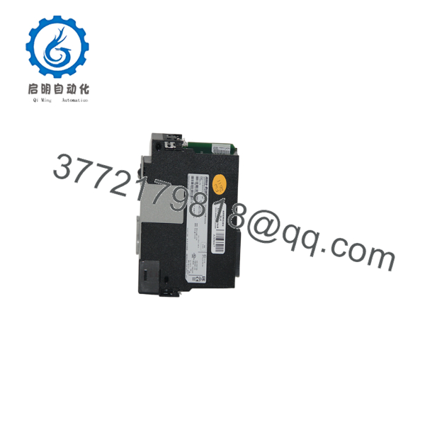
1756-L75
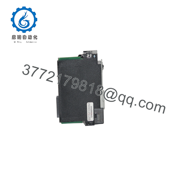
1756-L75
Installation & Configuration Guide
Stage 1 – Pre-Installation Preparation (Estimated Time: 15 Minutes)
⚠️ Safety First
- Notify operations of scheduled downtime.
- Bring the machine or process to a safe operating state.
- Apply lockout/tagout procedures.
- Remove chassis power.
- Wait at least 5 minutes before servicing the controller.
Tools Required
- Grounded ESD wrist strap
- PH1 screwdriver
- Fluke 115 digital multimeter
- Laptop with Studio 5000 Logix Designer
- USB programming cable
- Smartphone for documentation
Data Backup
- Upload the complete Studio 5000 project.
- Record the controller firmware revision.
- Backup the controller to the SD card if configured.
- Save network configuration.
- Photograph chassis slot assignments.
- Record module electronic keying settings.
Stage 2 – Removing the Existing Controller (Estimated Time: 10 Minutes)
- Verify chassis power is OFF.
- Disconnect the USB cable.
- Remove the SD card only if required.
- Label network and communication modules.
- Release the locking tabs.
- Remove the controller using straight, even pressure.
- Inspect the backplane connector for contamination or bent pins.
⚠️ Retain the original controller until the replacement completes production testing successfully.
Stage 3 – Installing the New Controller (Estimated Time: 20 Minutes)
- Wear a grounded ESD wrist strap.
- Confirm the replacement part number is 1756-L75.
- Verify the 1756-ESMCAP Energy Storage Module is installed.
- Insert the controller completely into the chassis.
- Verify the Secure Digital card is properly seated.
- Connect the USB programming cable.
- Verify firmware compatibility before downloading the application.
Self-Checklist
- Correct catalog number
- SD card installed
- Energy Storage Module installed
- Firmware verified
- Controller fully seated
Stage 4 – Power-On & Testing (Estimated Time: 30 Minutes)
Pre-Power Checks
- Verify chassis power supply output.
- Confirm Energy Storage Module status.
- Verify SD card installation.
- Inspect communication modules.
Commissioning Steps
- Apply chassis power.
- Verify the OK and RUN indicators.
- Connect with Studio 5000.
- Confirm firmware revision.
- Verify controller identity.
- Download or validate the project.
- Test all local and remote I/O before releasing the machine.
⚠️ Troubleshooting Notes
- Major Fault LED: Verify firmware compatibility before downloading.
- Communication failure: Check communication modules rather than the controller itself because the L75 has no embedded Ethernet port.
- Application recovery failure: Verify SD card configuration.
- Unexpected startup behavior: Confirm the Energy Storage Module is operating correctly.
Common Field Pitfalls
❗ Firmware Revision Mismatch
I’ve seen controllers sit in Program mode for hours because someone replaced hardware without recording the original firmware. Always document the existing revision before removing the controller. Firmware compatibility remains one of the most common causes of commissioning delays.
❗ Secure Digital Card Configuration
The SD card can automatically restore projects depending on controller configuration. Before replacing the processor, verify whether the card contains the current application or an older backup that could overwrite recent program changes.
❗ Energy Storage Module
Unlike older processors that used lithium batteries, the L75 stores volatile memory using the removable 1756-ESMCAP. A failed module can affect retained data during power interruptions.
❗ Communication Module Assumptions
This controller does not include an embedded EtherNet/IP port. Ethernet, ControlNet, or DeviceNet communication requires separate ControlLogix communication modules. I’ve seen engineers spend hours troubleshooting a “missing Ethernet port” that simply doesn’t exist on this CPU.
❗ Electrostatic Discharge
Always handle the controller on an ESD-safe surface while wearing a grounded wrist strap. Static damage may not be immediately visible but can shorten controller life.
Keep these checks in mind and you’ll avoid most ControlLogix processor replacement problems before production resumes.
Frequently Asked Questions (FAQ)
Q1. Is the Allen-Bradley 1756-L75 still available?
Yes.
Rockwell Automation currently lists the 1756-L75 as Active Mature, meaning it remains available while customers gradually migrate to newer controller families. Replacement options also exist for future lifecycle planning.
Q2. Does the 1756-L75 include an Ethernet port?
No.
Unlike CompactLogix controllers, the 1756-L75 does not include embedded Ethernet. Network connectivity requires separate communication modules such as the 1756-EN2T, 1756-EN2TR, or other compatible ControlLogix communication modules.
Q3. Can I replace a 1756-L61 or L64 with a 1756-L75?
Usually yes, but not by simply swapping hardware.
Verify firmware compatibility, Studio 5000 project compatibility, electronic keying, memory requirements, and communication module revisions before installation. Larger memory alone does not guarantee a successful migration.
Q4. Will replacing the controller erase my PLC program?
Not if proper backups exist.
Upload the complete Studio 5000 project, verify the SD card contents, and record the firmware revision before removing the original controller. Those three steps eliminate most recovery issues encountered during field replacements.
Q5. Why does the 1756-L75 use an Energy Storage Module instead of a battery?
The 1756-ESMCAP capacitor module replaces the lithium battery used in earlier generations. It provides temporary power for memory retention during power removal while reducing scheduled battery maintenance requirements.
Q6. How is each 1756-L75 tested before shipment?
Each controller should complete a documented quality process:
- Inbound Inspection & Traceability
- Verify OEM serial numbers.
- Inspect housing, PCB, USB connector, and backplane connector.
- Check for corrosion, repairs, scratches, and UV discoloration.
- Functional Testing
- Install in a genuine ControlLogix chassis.
- Verify startup diagnostics.
- Test USB communications.
- Download and execute a validation project.
- Operate continuously for more than 24 hours while monitoring processor status.
- Electrical Testing
- Verify insulation resistance where applicable.
- Check ground continuity.
- Measure controller current consumption.
- Firmware & Configuration Verification
- Record firmware revision.
- Verify SD card operation.
- Inspect the Energy Storage Module.
- Validate controller memory retention.
- Final QC & Packaging
- QC inspector approval.
- Anti-static ESD packaging.
- Heavy-duty corrugated shipping carton.
- QC Passed label with inspection date.
Test reports, photographs, and startup videos should be available upon request.
Q7. What should I verify before installing a replacement 1756-L75?
Before commissioning, verify:
- Exact catalog number (1756-L75)
- Firmware revision
- Studio 5000 compatibility
- SD card contents
- Energy Storage Module condition
- Communication module configuration
- Electronic keying settings
- Chassis power capacity
From practical field experience, the most common causes of delayed startup are firmware mismatches, outdated SD card images, and incorrect communication module configuration—not defective processors. Careful documentation before removing the original controller usually prevents hours of unnecessary troubleshooting.



