
 WhatsApp: +86 16626708626
 Email:
  Phone: +86 16626708626
Description
3. Key Technical Specifications
| Parameter | Specification Value |
|---|---|
| Catalog Part Number | 1756-RM |
| Manufacturer | Allen-Bradley (Rockwell Automation) |
| Compatible Architecture | Allen-Bradley ControlLogix (1756 Chassis System) |
| Redundancy Link Rate | 1000 Mbps fiber-optic cross-chassis link |
| Fiber Cable Type | LC-connector multimode fiber optic cable (1756-RMCx series) |
| Max Fiber Distance | Up to 10 km (using single-mode fiber transceiver options/1756-RM2) |
| Backplane Power Draw | 1.2 A @ 5.1V DC, 120 mA @ 24V DC (Total ~7.0 W) |
| Switchover Time | < 10 ms (bump-less lockstep switchover) |
| Chassis Slot Requirement | 1 slot per chassis in identical slot locations |
| Operating Temperature | 0°C to +60°C (32°F to 140°F) |
| Status Display | Alpha-numeric diagnostic display and LED indicators |
4. Product Introduction & Supply Chain Strategy
The Allen-Bradley 1756-RM is a dedicated fiber-optic redundancy module engineered for ControlLogix fault-tolerant controller pairs. Installed in paired, identical ControlLogix chassis, the 1756-RM continuously synchronizes memory, tag values, I/O state tables, and task execution contexts between the Primary and Secondary chassis. In the event of a primary controller or power supply fault, it executes a bump-less switchover to the secondary system in milliseconds, preventing process interruption or valve tripping.
This product is a Brand New Surplus unit. It is not used, not pulled from a decommissioned plant, and not refurbished. All modules undergo rigorous quality verification to ensure OEM-level reliability.
Securing the 1756-RM as New Surplus eliminates high-risk failure vectors in critical control loops. Refurbished redundancy modules often contain worn fiber-optic transceivers, degraded memory buffers, or aged power delivery components that risk cross-chassis sync loss or false switchovers. Sourcing verified New Surplus provides original factory link speed and synchronization integrity while avoiding extended manufacturer lead times.
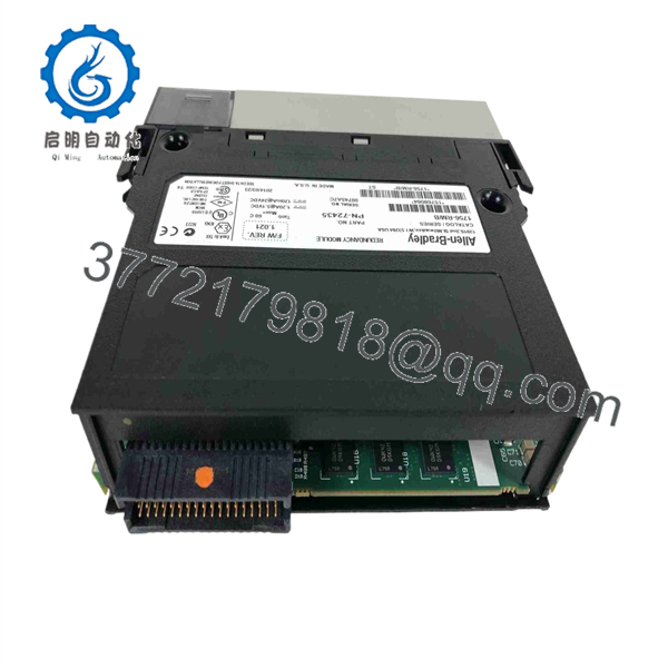
1756-RM
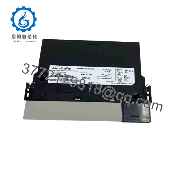
1756-RM
5. Installation & Configuration Guide
Stage 1: Pre-Installation (Prep & Safety)
- Open the main incoming AC power breakers feeding both redundant ControlLogix racks and apply Lock-Out/Tag-Out (LOTO).
- Attach a grounded ESD wrist strap before handling the 1756-RM card or fiber optic patch cables.
- Verify that both chassis are built with identical hardware, power supplies, module slot placement, and firmware revisions.
- Clean fiber-optic cable connectors and module ports using an optical cleaning tool before insertion.
Stage 2: Removal
- Carefully press the fiber cable connector release tab and pull the fiber patch cable out of the module front panel.
- Depress the top and bottom chassis locking tabs on the 1756-RM module.
- Slide the card straight out along the chassis guide rails to protect the rear backplane connector.
- Store the removed module in an ESD protective bag.
Stage 3: Installation (Clone & Seat)
- Align the 1756-RM circuit board with the designated chassis slot (must match the exact slot number in both primary and secondary racks).
- Slide the module firmly into the slot until top and bottom retention tabs snap into place.
- Connect the 1756-RMC fiber-optic cable between the
CH1fiber ports of the primary and secondary 1756-RM modules.
Stage 4: Power-On & Testing
- Restore power to both ControlLogix chassis power supplies.
- Monitor the alpha-numeric status display on the front panel: one chassis should display
PRIM(Primary) and the second should displaySYNCorSTATduring synchronization. - Verify full system redundancy in Studio 5000 Logix Designer using the Redundancy Module Configurator tool.
- Perform a controlled switchover test via Studio 5000 or physical switch disconnect to confirm bump-less transfer.
6. Firmware/Software Versions & Upgrade Notes
The 1756-RM operates in tight lockstep with ControlLogix controller firmware revisions.
- Firmware Bundles: Redundancy systems require matching firmware bundle revisions across all processors (1756-L7x/L8x), Ethernet modules (1756-EN2T/EN2TR), and redundancy modules (1756-RM).
- 1756-RM vs 1756-RM2: The enhanced 1756-RM2 provides higher fiber bandwidth, faster cross-chassis sync times, and native support for ControlLogix 5580 (1756-L8x) controllers.
- Fiber Cables: Always use Rockwell-approved fiber optic patch cables (1756-RMC1, 1756-RMC3, 1756-RMC10) or certified single-mode equivalents to prevent signal loss across the redundancy link.
7. Frequently Asked Questions (FAQ)
Q: Is this 1756-RM module brand new or has it been pulled from a decommissioned plant?
A: This product is a Brand New Surplus unit. It is not used, not pulled from a decommissioned plant, and not refurbished. All modules undergo rigorous quality verification to ensure OEM-level reliability.
Q: What is the main difference between 1756-RM and 1756-RM2?
A: The 1756-RM2 is a higher-performance generation module that supports faster synchronization throughput, dual fiber optic channels for physical link redundancy, and full compatibility with ControlLogix L8 series controllers.
Q: Do I need to program logic for the 1756-RM to execute a switchover?
A: No. The 1756-RM handles hardware and state synchronization automatically at the system level. Studio 5000 provides status tags for diagnostics, but cross-chassis switchover is managed transparently by module hardware.
Q: Can I use different slot positions for the 1756-RM in the primary and secondary chassis?
A: No. Redundant ControlLogix architectures require identical chassis sizes, module types, and exact slot layout configurations in both the primary and secondary racks.
Q: What warranty applies to this New Surplus module?
A: We back this module with a full 1-year functional replacement warranty from the date of shipment, ensuring maximum process reliability and zero financial risk.



