WhatsApp: +86 16626708626
 Email:
 Phone: +86 16626708626
Description
Core Product Summary (Brand / Model / Key Attributes)
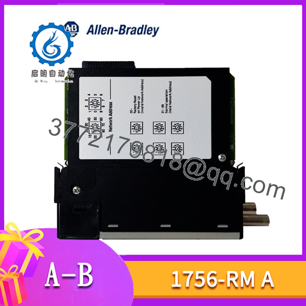
The Allen-Bradley 1756-RM Series A (1756-RM-A) is a dedicated hardware redundancy module within the ControlLogix system architecture, designed to establish high-availability, fault-tolerant controller pairings. Installed into a standard ControlLogix 1756 chassis, the module connects a primary controller chassis directly to a secondary standby chassis via a single-mode fiber-optic link. It manages automatic cross-loading of control program logic, I/O state data, internal memory tags, and system diagnostics to ensurebumpless failover without process interruption.
Designed for single-slot installation, the 1756-RM Series A draws power directly from the 1756 backplane (1.2 A at 5.1V DC and 120 mA at 24V DC) with a total power dissipation rating of 9 W. The front panel features a single-mode fiber-optic channel interface utilizing standard LC connectors, supporting high-speed cross-chassis synchronization over distance. It operates seamlessly across 1756 chassis options (such as 1756-A4, 1756-A7, 1756-A10, 1756-A13, and 1756-A17) to provide high-reliability synchronization for ControlLogix L6x and L7x control systems.
Key Technical Specifications
| Specification Parameter | Verified Value / Range |
| Manufacturer / Brand | Allen-Bradley / Rockwell Automation |
| Catalog / Series | 1756-RM Series A (1756-RM-A) |
| System Architecture | ControlLogix Chassis-Based System |
| Module Function | High-Availability Controller Synchronization / Redundancy |
| Backplane Current Draw | 4 mA @ 1.2V DC, 1.2 A @ 5.1V DC, 120 mA @ 24V DC |
| Maximum Power Dissipation | 9.0 W (Thermal Dissipation: approx. 31 BTU/hr) |
| Physical Slot Width | 1 Slot (Standard ControlLogix Chassis Slot) |
| Fiber Optic Cable Interface | LC-type connector, single-mode fiber optic |
| Compatible Redundancy Cables | 1756-RMC1 (1 m), 1756-RMC3 (3 m), 1756-RMC10 (10 m) |
| Operating Temperature Range | 0°C to +60°C (+32°F to +140°F) |
| Non-Operating (Storage) Temp | -40°C to +85°C (-40°F to +185°F) |
| Operating Relative Humidity | 5% to 95% (non-condensing) |
| Operating Shock & Vibration | 30 g operating shock / 2 g at 10–500 Hz vibration |
| Compatible Chassis Types | 1756-A4, 1756-A7, 1756-A10, 1756-A13, 1756-A17 |
Detailed Product Overview
The Allen-Bradley 1756-RM Series A ControlLogix Redundancy Module plays a central role in high-availability automation applications where process downtime presents severe operational risk. Functioning as an inter-chassis hardware bridge, the module monitors the integrity of the primary controller and continuously mirrors data to a redundant secondary chassis. During normal operation, data synchronization occurs deterministically across the dedicated fiber link at the conclusion of task execution cycles, maintaining exact state alignment between primary and secondary controller memory.
In the event of a primary chassis fault, power loss, controller trip, or network disconnect, the secondary 1756-RM module detects the interruption and executes an immediate, transparent switchover. The standby controller instantly assumes command of the process without resetting control logic, dropping network connections, or disturbing field outputs. The module’s front panel displays diagnostic status LEDs indicating primary/secondary state assignment, module health, optical link status, and data synchronization activity.
Designed for simple integration into standard 1756 chassis backplanes, the 1756-RM-A operates alongside compatible ControlLogix processors and communications modules (such as EtherNet/IP 1756-EN2T/EN3TR or ControlNet 1756-CN2R modules). Dedicated software configuration tools within Studio 5000 Logix Designer allow engineers to assign redundancy parameters, monitor switchover health, and conduct system synchronization diagnostics.
1756-RM-A
Engineering Selection Highlights
- Automatic Deterministic Synchronization: Continuously mirrors program state, memory tags, and I/O data over a dedicated fiber-optic link to enable bumpless transfer during controller failure.
- Single-Slot Backplane Form Factor: Integrates directly into standard ControlLogix 1756 chassis slots without requiring external rack adapters or specialized mounting hardware.
- Galvanic & Electrical Isolation via Fiber: Employs single-mode LC fiber-optic media to eliminate electrical noise interference, ground loops, and potential cross-chassis electrical faults.
- Integrated Hardware Diagnostics: Provides real-time visual diagnostics via front-panel LED indicators to verify link connection status, node qualification, and active primary/standby roles.
- High-Availability Compatibility: Designed to function alongside standard redundant 1756 power supply systems (such as 1756-PA75R/PB75R) and redundant network modules for comprehensive system fault-tolerance.
System Compatibility & Integration Requirements
| Item / Dependency | Verified Compatibility or Requirement | Practical Note |
| Supported System Platform | Allen-Bradley ControlLogix System | Requires identical chassis layouts between primary and secondary pairs. |
| Chassis Compatibility | 1756-A4, 1756-A7, 1756-A10, 1756-A13, 1756-A17 | Must be placed in identical slot positions within both redundant chassis. |
| Redundancy Interconnect Cables | 1756-RMC1, 1756-RMC3, 1756-RMC10 | Standard factory single-mode fiber cables; maintain specified minimum bend radius during routing. |
| Controller Hardware | Identical ControlLogix controllers (e.g., paired 1756-L6x or 1756-L7x) | Both chassis must contain matching controller hardware and identical firmware revisions. |
| System Software Tool | RSLogix 5000 / Studio 5000 Logix Designer | Uses the Redundancy Module Configuration Tool for system diagnostics and firmware management. |
Dimensions, Mounting & Connection Notes
- Physical Size: Standard 1-slot ControlLogix module profile (approx. 145 mm H x 35 mm W x 140 mm D).
- Mounting Configuration: Direct snap-in insertion into any available slot of a 1756 chassis backplane; requires identical slot alignment between primary and secondary chassis.
- Fiber Optic Connection: Single-mode LC duplex port located on the front panel. Ensure protective dust covers remain on optical ports when no cable is connected.
- Fiber Bend Radius: Maintain a minimum bend radius of 12.7 cm (5.0 in.) along the fiber-optic cable path to prevent signal attenuation and optical loss.
- Backplane Power Allocation: Ensure cabinet power supplies are sized to accommodate the module’s 1.2 A draw at 5.1V DC and 120 mA draw at 24V DC.
FAQ
What is the primary purpose of the Allen-Bradley 1756-RM-A?
The 1756-RM-A is a ControlLogix redundancy module that links two identical ControlLogix chassis via fiber optics to provide automatic data synchronization and continuous controller failover capability.
What fiber-optic cables are compatible with the 1756-RM-A?
The module utilizes standard single-mode fiber cables with LC connectors, including Allen-Bradley 1756-RMC1 (1 m), 1756-RMC3 (3 m), and 1756-RMC10 (10 m) cable assemblies.
Can a 1756-RM module be mixed with a 1756-RM2 module in the same redundant pair?
No. The 1756-RM and 1756-RM2 modules use different communication protocols and hardware architectures, and cannot be paired together across a redundant link.
What are the power supply requirements for the 1756-RM Series A?
The module receives power directly from the 1756 backplane, drawing 1.2 A at 5.1V DC, 120 mA at 24V DC, and 4 mA at 1.2V DC, with a maximum thermal dissipation of 9 W.
Does the primary and secondary chassis require matching slot layouts?
Yes. For complete redundancy qualification, both the primary and standby chassis must use identical hardware, matching slot assignments, and identical module firmware versions.
Verification & Troubleshooting Notes
- Link Status LED: If the front-panel fiber channel LED is unlit or flashing red, check the fiber cable for physical damage, verify the minimum cable bend radius, and ensure LC connectors are fully seated.
- Qualification Failures: If the secondary chassis fails to reach “Synchronized” or “Qualified” state, verify that all hardware modules, controller firmware versions, and network communication configurations match between both chassis.
- Backplane Power Load Check: Excessive voltage drop on the 5.1V DC backplane rail can prevent module startup. Verify total chassis power consumption against the capacity of the installed 1756 power supply module.