
 WhatsApp: +86 16626708626
 Email:
  Phone: +86 16626708626
Description
Key Technical Specifications
| Parameter | Value |
|---|---|
| Product Type | Redundancy Module Cable |
| Catalog Number | 1757-SRC1 |
| Cable Length | 1 m (3 ft) |
| Application | ControlLogix System Redundancy |
| Compatible Module | 1757-SRM |
| Fiber Type | 62.5/125 μm Multimode Fiber |
| Connector Type | Factory-terminated connectors for 1757-SRM |
| Maximum Standard Distance | 100 m using standard SRC cable family |
| Installation | Direct connection between primary and secondary chassis |
| Operating Purpose | High-speed synchronization between redundant controllers |
| Manufacturer | Rockwell Automation |
The 1757-SRC1 is a 1-meter redundancy module cable designed specifically to connect two 1757-SRM System Redundancy Modules in a ControlLogix redundant controller system. It is one member of the SRC cable family, which also includes 3 m, 10 m, 50 m, and 100 m versions.
Product Introduction
The Allen-Bradley 1757-SRC1 is a dedicated fiber-optic communication cable used in legacy ControlLogix redundancy systems. It provides the high-speed synchronization link between the primary and secondary 1757-SRM modules, allowing controller state information to be continuously mirrored for automatic switchover during a controller failure.
Unlike a standard Ethernet or industrial fiber cable, the 1757-SRC1 is engineered specifically for Rockwell Automation redundancy hardware. Using substitute fiber assemblies or incorrect connector types can prevent redundant synchronization or generate redundancy faults during commissioning.
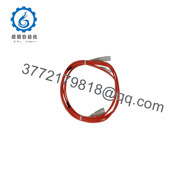
1757-SRC1
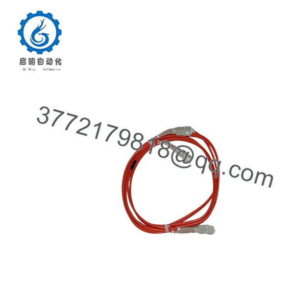
1757-SRC1
Installation & Configuration Guide
Stage 1 – Pre-Installation Preparation (5 Minutes)
⚠️ Safety First
- Notify plant operations.
- Place the redundant system into a maintenance window.
- Shut down both controller chassis if required by site procedures.
- Wear an ESD wrist strap before handling fiber connections.
Required Tools
- Fiber cleaning kit
- ESD wrist strap
- Flashlight
- Cable labels
- Optical inspection scope (recommended)
Stage 2 – Remove Existing Cable (5 Minutes)
- Verify redundancy synchronization is stopped.
- Disconnect the cable from both 1757-SRM modules.
- Install dust caps immediately.
- Inspect connectors for contamination or damage.
⚠️ Never pull the fiber by the cable jacket. Always grip the connector body.
Stage 3 – Install the New Cable (10 Minutes)
- Verify the cable is 1757-SRC1 (1 m).
- Clean both fiber connectors before installation.
- Connect one end to the primary 1757-SRM.
- Connect the opposite end to the secondary 1757-SRM.
- Route the cable away from high-voltage conductors.
- Maintain the minimum bend radius specified for fiber-optic cable.
Installation Checklist
- ✔ Correct cable length
- ✔ Connectors fully seated
- ✔ No sharp bends
- ✔ Fiber cleaned before installation
Stage 4 – System Verification (10–15 Minutes)
- Power both redundant chassis.
- Verify both 1757-SRM modules initialize normally.
- Confirm redundancy synchronization completes successfully.
- Check controller diagnostics for communication errors.
- Perform a controlled redundancy switchover test if permitted by plant procedures.
⚠️ Troubleshooting
- Redundancy synchronization failure: inspect connector cleanliness and cable routing.
- Communication timeout: verify both SRM modules are compatible and correctly configured.
- Intermittent faults: inspect the fiber for excessive bending or physical damage.
Frequently Asked Questions
Q1. What is the 1757-SRC1 used for?
It is a dedicated 1-meter fiber-optic cable that connects two 1757-SRM System Redundancy Modules, enabling continuous synchronization between the primary and secondary ControlLogix controllers.
Q2. Can I replace it with a standard fiber-optic patch cable?
No. The 1757- is designed specifically for the 1757-SRM redundancy architecture. Using an incorrect cable or connector type may prevent the redundancy system from synchronizing correctly.
Q3. What cable lengths are available?
Rockwell Automation offers multiple standard lengths:
- – 1 m
- 1757-SRC3 – 3 m
- 1757-SRC10 – 10 m
- 1757-SRC50 – 50 m
- 1757-SRC100 – 100 m
Q4. What is the maximum distance between redundant chassis?
Using standard SRC cables, redundant chassis can be separated by up to 100 m (300 ft). For greater distances, Rockwell recommends a custom multimode fiber installation meeting specific optical loss and connector requirements.
Q5. Is the 1757- still widely used?
Although intended for legacy ControlLogix redundancy systems, it remains in service in many facilities that continue to operate 1757-SRM-based redundant controller architectures. Replacement cables are commonly sourced as new surplus or tested used inventory.
Q6. What should I inspect before commissioning?
Verify:
- Correct catalog number ()
- Fiber connector cleanliness
- Proper routing without excessive bending
- Secure connector engagement
- Matching 1757-SRM module configuration
- Successful redundancy synchronization after startup
One of the most common field issues is contamination on fiber connectors. Even a small amount of dust can increase optical loss enough to prevent redundant controllers from synchronizing reliably. Always clean and inspect both connectors before powering the system.



