
 WhatsApp: +86 16626708626
 Email:
  Phone: +86 16626708626
Description
Key Technical Specifications
| Parameter | Value |
|---|---|
| Product Type | MicroLogix 1400 PLC Controller |
| Power Supply | 24 VDC |
| Digital Inputs | 20 (12 high-speed + 8 standard) |
| Digital Outputs | 12 (6 relay + 3 high-speed FET + 3 standard FET) |
| Analog Inputs | 4 channels, 0–10 VDC, 12-bit |
| Analog Outputs | 2 channels, 0–10 VDC, 12-bit |
| User Memory | 20 KB |
| Ethernet Port | Embedded 10/100 Mbps EtherNet/IP |
| Serial Ports | One isolated RS-232/RS-485 and one non-isolated RS-232 |
| High-Speed Functions | PTO, PWM, High-speed Counter |
| Expansion | Supports 1762 Expansion I/O |
| Mounting | DIN Rail or Panel Mount |
The 1766-L32BXBA is a MicroLogix 1400 controller powered by 24 VDC, featuring 20 digital inputs, 12 digital outputs, 4 integrated analog inputs, 2 analog outputs, embedded Ethernet, and two serial communication ports.
Product Introduction
The Allen-Bradley 1766-L32BXBA is the most feature-rich controller in the MicroLogix 1400 family. It combines high-speed digital I/O, integrated analog I/O, Ethernet networking, and serial communications in a compact controller designed for OEM equipment, water treatment, material handling, packaging machines, and process automation.
Unlike earlier MicroLogix controllers that require separate analog expansion modules, the 1766-L32BXBA integrates both analog inputs and outputs. This reduces cabinet space, simplifies wiring, and lowers installation costs while maintaining compatibility with existing RSLogix 500 applications.
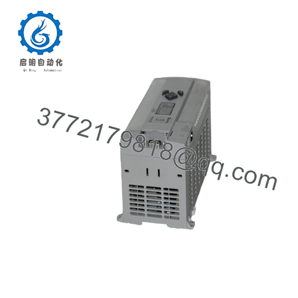
1766-L32BXBA
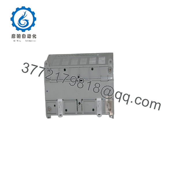
1766-L32BXBA
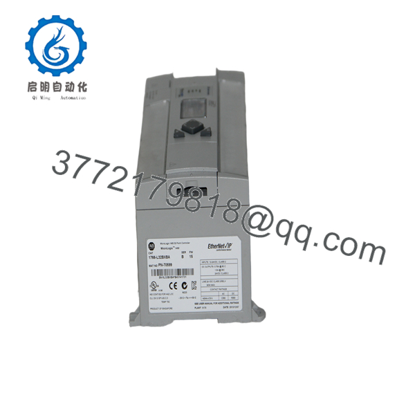
1766-L32BXBA
Installation & Configuration Guide
Stage 1 – Pre-Installation Preparation (5–10 Minutes)
⚠️ Safety First
- Notify plant personnel of the scheduled shutdown.
- Apply Lock-Out/Tag-Out procedures.
- Disconnect the 24 VDC power supply.
- Verify zero voltage before servicing.
Required Tools
- ESD wrist strap
- Digital multimeter
- Small Phillips screwdriver
- Laptop with RSLogix 500
- Ethernet patch cable
Before Removal
- Upload the PLC project.
- Record the Ethernet IP address.
- Document serial communication settings.
- Photograph all field wiring.
Stage 2 – Remove Existing Controller (5 Minutes)
- Verify power is OFF.
- Disconnect Ethernet and serial cables.
- Label and disconnect all field wiring.
- Remove expansion I/O modules if installed.
- Release the DIN rail clip and remove the controller.
⚠️ Keep the original controller until the replacement has completed commissioning successfully.
Stage 3 – Install the New Controller (10 Minutes)
- Verify the replacement catalog number is 1766-L32BXBA.
- Mount the controller securely.
- Reconnect expansion I/O modules.
- Connect the 24 VDC supply.
- Restore all digital and analog field wiring.
- Configure the Ethernet IP address if required.
Installation Checklist
- ✔ Correct catalog number
- ✔ 24 VDC supply verified
- ✔ Ethernet communication confirmed
- ✔ Analog wiring checked
- ✔ Expansion modules recognized
Stage 4 – Power-Up & Functional Testing (10–15 Minutes)
- Restore 24 VDC power.
- Verify the POWER and RUN indicators.
- Connect using RSLogix 500.
- Confirm Ethernet communication.
- Test all digital and analog I/O.
- Verify PTO, PWM, or high-speed counter functions if used.
⚠️ Troubleshooting
- No Ethernet communication: verify IP address and subnet mask.
- Analog input errors: confirm channel configuration and signal range.
- High-speed output issues: verify FET outputs are assigned correctly.
Frequently Asked Questions
Q1. What makes the 1766-L32BXBA different from other MicroLogix 1400 controllers?
It combines integrated analog inputs and outputs, embedded Ethernet, high-speed digital I/O, and 24 VDC power in one controller. This reduces the need for additional expansion modules.
Q2. Does this controller support EtherNet/IP?
Yes. The controller includes an integrated 10/100 Mbps Ethernet port supporting EtherNet/IP messaging, remote programming, and industrial networking.
Q3. Can I expand the I/O?
Yes. The 1766-L32BXBA supports 1762 expansion I/O modules, allowing additional digital and analog channels to be added as system requirements grow.
Q4. What programming software is required?
The controller is programmed using RSLogix 500 and is compatible with RSLinx Classic for communications and diagnostics.
Q5. What are the analog signal ranges?
The integrated analog I/O supports 0–10 VDC signals with 12-bit resolution. The analog outputs have a maximum settling time of 3 ms.
Q6. What should I verify before ordering?
Confirm the following:
- Catalog number ()
- 24 VDC power availability
- Required digital and analog I/O count
- Ethernet network configuration
- RSLogix 500 project compatibility
- Required 1762 expansion modules
A common commissioning issue is restoring the PLC program while overlooking the Ethernet configuration. Before returning the controller to service, verify the IP address, subnet mask, and communication settings to avoid unnecessary network troubleshooting.



