
 WhatsApp: +86 16626708626
 Email:
  Phone: +86 16626708626
Description
Key Technical Specifications
| Parameter | Value |
|---|---|
| Product Type | Isolated Analog Input Module |
| Series | 1769 Compact I/O |
| Number of Inputs | 4 isolated differential inputs |
| Voltage Input Ranges | ±10 VDC, 0–10 VDC, 0–5 VDC, 1–5 VDC |
| Current Input Ranges | 0–20 mA, 4–20 mA |
| Resolution | 16-bit (unipolar), 15-bit + sign (bipolar) |
| Converter Type | Delta-Sigma A/D |
| Isolation | Channel-to-channel and channel-to-backplane isolation |
| Input Impedance | 1 MΩ (Voltage), 249 Ω (Current) |
| Bus Current Draw | 140 mA @ 5 VDC, 110 mA @ 24 VDC |
| Maximum Heat Dissipation | 3.0 W |
| Operating Temperature | 0 °C to 60 °C |
| Mounting | DIN Rail or Panel Mount |
The 1769-IF4I is a four-channel isolated differential analog input module that supports multiple voltage and current input ranges, including ±10 VDC, 0–10 VDC, 0–5 VDC, 1–5 VDC, 0–20 mA, and 4–20 mA. It provides 16-bit unipolar and 15-bit bipolar resolution with channel-to-channel isolation for improved measurement accuracy in electrically noisy environments.
Product Introduction
The Allen-Bradley 1769-IF4I is designed for CompactLogix and Compact I/O systems that require accurate acquisition of analog process signals while maintaining electrical isolation between channels. It accepts both voltage and current inputs from transmitters, pressure sensors, flow meters, level instruments, and other industrial field devices.
Unlike standard analog input modules that share a common reference, each channel on the 1769-IF4I is electrically isolated. This significantly reduces the effects of ground loops and electrical noise, making the module well suited for process control applications where sensors are distributed across different grounding systems.
The module uses Delta-Sigma analog-to-digital conversion technology and configurable digital filtering to provide stable measurements while maintaining excellent noise rejection. It integrates seamlessly with CompactLogix and other controllers supporting the 1769 Compact I/O platform.
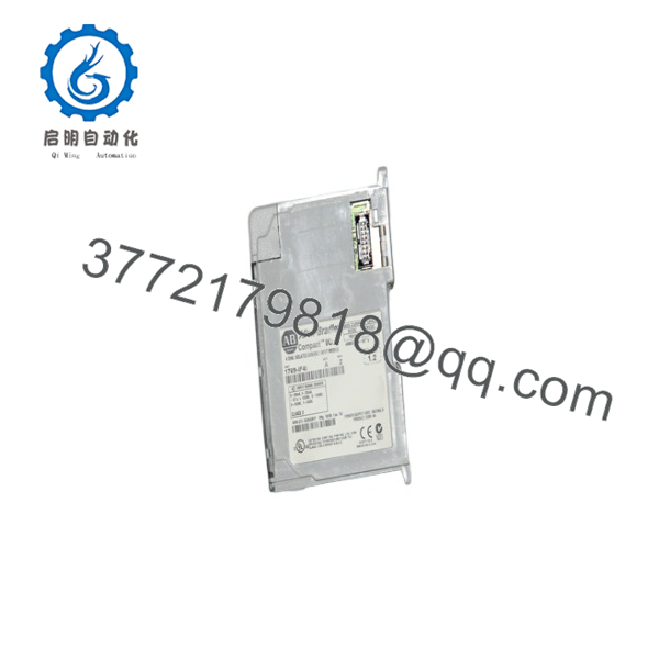
1769-IF4I
Installation & Configuration Guide
Stage 1 – Pre-Installation Preparation (5–10 Minutes)
⚠️ Safety First
- Notify plant personnel of scheduled maintenance.
- Apply Lock-Out/Tag-Out procedures.
- Disconnect system power.
- Verify all analog loops are de-energized.
Required Tools
- ESD wrist strap
- Digital multimeter
- Small flat-blade screwdriver
- Shielded analog signal cable (Belden 8761 or equivalent)
- Laptop with Studio 5000 Logix Designer
Before Removal
- Back up the controller project.
- Record channel configuration.
- Label all analog wiring.
- Photograph terminal connections.
Stage 2 – Remove Existing Module (5 Minutes)
- Confirm power is OFF.
- Disconnect all field wiring.
- Release the module locking tabs.
- Remove the module carefully.
- Inspect the Compact I/O bus connectors.
⚠️ Do not force the module from the bus connector.
Stage 3 – Install the New Module (10 Minutes)
- Verify the replacement is 1769-IF4I.
- Install the module onto the Compact I/O bus.
- Secure the retaining mechanism.
- Reconnect the field wiring.
- Configure each channel for the required voltage or current range.
- Verify terminal torque.
Installation Checklist
- ✔ Correct catalog number
- ✔ Signal type configured
- ✔ Shield grounding verified
- ✔ Bus connector fully engaged
Stage 4 – Commissioning & Functional Testing (10–15 Minutes)
- Restore system power.
- Verify the Module Status indicator.
- Confirm communication with the controller.
- Apply calibrated analog signals.
- Verify scaling and engineering units.
- Confirm all channels report stable measurements.
⚠️ Troubleshooting
- Over-range alarms typically indicate the input exceeds the configured operating range.
- Unstable readings often result from improper cable shielding or grounding.
- No input signal may indicate incorrect channel configuration or wiring errors.
Frequently Asked Questions
Q1. What signal types does the 1769-IF4I support?
The module supports ±10 VDC, 0–10 VDC, 0–5 VDC, 1–5 VDC, 0–20 mA, and 4–20 mA input signals, allowing it to interface with a wide variety of industrial sensors and transmitters.
Q2. Why is channel isolation important?
Each of the four inputs is electrically isolated from the other channels and from the backplane. This minimizes ground-loop currents, improves noise immunity, and enhances measurement reliability in distributed process applications.
Q3. Which controllers are compatible?
The 1769-IF4I is compatible with CompactLogix, Compact I/O, and selected MicroLogix 1500 systems that support 1769 expansion modules.
Q4. What is the measurement resolution?
The module provides 16-bit resolution for unipolar ranges and 15-bit plus sign for bipolar ranges, enabling accurate analog signal acquisition.
Q5. What type of cable is recommended?
Rockwell Automation recommends using Belden 8761 or an equivalent shielded cable for analog signal wiring to reduce electrical interference and maintain measurement accuracy.
Q6. What should I verify before ordering?
Confirm the following:
- Catalog number ()
- Controller compatibility
- Required input signal type (Voltage or Current)
- Number of analog channels
- Power supply capacity
- Available Compact I/O expansion slot
- Firmware and Studio 5000 compatibility
One of the most common startup issues is configuring the wrong input type for a channel—for example, assigning a 4–20 mA transmitter to a 0–10 VDC input configuration. Verifying both the field wiring and the software configuration before commissioning can prevent incorrect process readings and reduce troubleshooting time.



