
 WhatsApp: +86 16626708626
 Email:
  Phone: +86 16626708626
Description
Key Technical Specifications
| Parameter | Value |
|---|---|
| Product Type | Digital DC Input Module |
| Series | 1769 Compact I/O |
| Number of Inputs | 32 |
| Input Groups | 4 groups (8 inputs per group) |
| Input Voltage | 24 VDC Nominal |
| Operating Voltage Range | 10–30 VDC (10–26.4 VDC at 60°C) |
| Input Type | Sink/Source |
| On-State Voltage | ≥10 VDC |
| Off-State Voltage | ≤5 VDC |
| Input Delay | 8 ms ON / 8 ms OFF |
| Bus Current Draw | 170 mA @ 5.1 VDC |
| Isolation | 1200 VAC for 1 s (point-to-bus and group-to-group) |
| Operating Temperature | 0°C to 60°C |
| Mounting | DIN Rail or Panel Mount |
The 1769-IQ32 is a 32-point, 24 VDC sink/source digital input module for the Compact I/O platform. It supports 10–30 VDC input signals, provides 32 inputs divided into four groups of eight channels, and features reinforced isolation between input groups and the Compact I/O bus. Rockwell Automation currently classifies the product as Active Mature.
Product Introduction
The Allen-Bradley 1769-IQ32 is a high-density discrete input module designed for CompactLogix, Compact I/O, and compatible distributed I/O systems. It monitors the ON/OFF status of field devices such as pushbuttons, selector switches, proximity sensors, limit switches, and auxiliary contacts, converting these signals into data for the controller.
With 32 digital inputs in a compact form factor, the module maximizes cabinet space while reducing wiring costs compared to multiple lower-density modules. Its four isolated input groups improve electrical noise immunity and simplify field wiring for applications where sensors are powered from different supply circuits.
The 1769-IQ32 is commonly installed in packaging machinery, conveyor systems, automotive manufacturing, water treatment facilities, material handling systems, and OEM automation equipment. It can be used as local CompactLogix I/O or as remote I/O through communication adapters such as the 1769-AENTR.
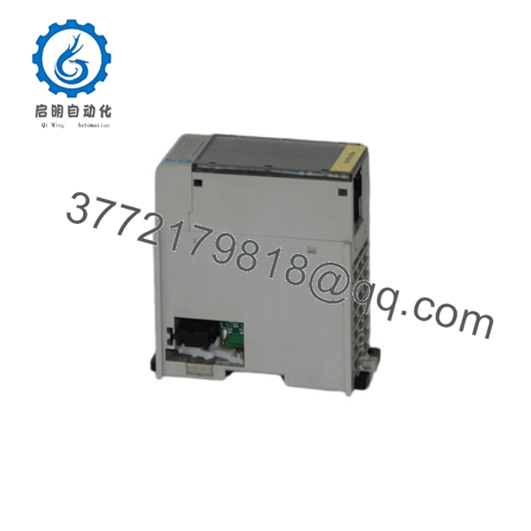
1769-IQ32
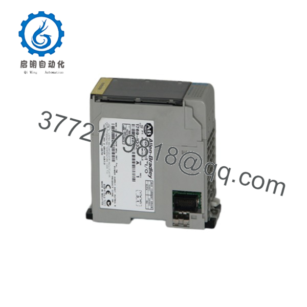
1769-IQ32
Installation & Configuration Guide
Stage 1 – Pre-Installation Preparation (5–10 Minutes)
⚠️ Safety First
- Notify plant personnel before maintenance.
- Follow Lock-Out/Tag-Out procedures.
- Remove system power.
- Verify all field circuits are de-energized.
Required Tools
- ESD wrist strap
- Digital multimeter
- Small flat-blade screwdriver
- Wire identification labels
- Studio 5000 Logix Designer
Before Removal
- Upload the controller project.
- Record module slot location.
- Label all field wiring.
- Photograph terminal connections.
Stage 2 – Remove Existing Module (5 Minutes)
- Confirm power is OFF.
- Disconnect the terminal block wiring.
- Release the module locking mechanism.
- Remove the module from the Compact I/O assembly.
- Inspect side-bus connectors for contamination or damage.
⚠️ Do not force the module from the bus connector.
Stage 3 – Install the New Module (10 Minutes)
- Verify the replacement catalog number is 1769-IQ32.
- Install the module onto the Compact I/O bus.
- Lock the module securely.
- Reconnect all input wiring.
- Verify each input group common is wired correctly.
- Confirm terminal screws are tightened to specification.
Installation Checklist
- ✔ Correct catalog number
- ✔ 24 VDC field supply verified
- ✔ Input commons correctly wired
- ✔ Module fully seated
- ✔ Terminal block secured
Stage 4 – Commissioning & Functional Testing (10–15 Minutes)
- Restore system power.
- Verify the Module Status indicator.
- Confirm the controller recognizes the module.
- Test each input using field devices.
- Verify all input LEDs correspond to controller status.
- Confirm proper PLC logic operation.
⚠️ Troubleshooting
- Input not changing state: verify field voltage and common wiring.
- Multiple inactive channels: inspect the corresponding input group common.
- Intermittent signals: check sensor wiring, grounding, and cable routing.
- Communication fault: verify module placement and Compact I/O bus connections.
Frequently Asked Questions
Q1. What devices can be connected to the 1769-IQ32?
The module accepts 24 VDC discrete input signals from proximity sensors, photoelectric sensors, limit switches, pushbuttons, selector switches, relay contacts, and other industrial field devices.
Q2. Is the module compatible with CompactLogix?
Yes. The 1769-IQ32 is compatible with CompactLogix controllers, 1769 Compact I/O systems, and remote I/O architectures using adapters such as the 1769-AENTR.
Q3. How are the inputs organized?
The module provides 32 digital inputs divided into four groups of eight channels, allowing flexible wiring and improved electrical isolation between groups.
Q4. What is the operating voltage range?
The module accepts 10–30 VDC input signals under normal operating conditions, with a nominal voltage of 24 VDC.
Q5. Does the module require configuration?
Only minimal configuration is required. After adding the module in Studio 5000 Logix Designer, the controller automatically maps the 32 input points to the I/O data table.
Q6. What should I verify before ordering?
Confirm the following:
- Catalog number ()
- CompactLogix or compatible controller
- Required number of digital input channels
- 24 VDC field power availability
- Sink/source sensor compatibility
- Available Compact I/O expansion position
- Studio 5000 firmware compatibility
A common installation mistake is wiring the input group commons incorrectly. Because the divides its inputs into four independent groups, each group common must match the field power configuration. Verifying the common wiring before applying power can prevent multiple channels from remaining inactive and significantly reduce commissioning time.



