
 WhatsApp: +86 16626708626
 Email:
  Phone: +86 16626708626
Description
Key Technical Specifications
| Parameter | Value |
|---|---|
| Product Type | CompactLogix 5370 Controller |
| Series | 5370 L3 |
| User Memory | 2 MB |
| Ethernet Ports | Dual 10/100 Mbps RJ45 |
| Ethernet Protocol | EtherNet/IP |
| Maximum Ethernet/IP Nodes | 32 |
| Maximum TCP Connections | 120 |
| Maximum Local 1769 I/O Modules | 16 |
| Maximum Local I/O Points | 512 |
| Motion Control | Not Supported (Standard L33ER) |
| Memory Card | 1 GB Secure Digital (SD) Card |
| Battery | Not Required (Supercapacitor Backup) |
| Programming Software | Studio 5000 Logix Designer |
| Operating Temperature | 0°C to 60°C |
| Mounting | DIN Rail or Panel Mount |
The 1769-L33ER is a CompactLogix 5370 L3 controller with 2 MB of user memory, dual embedded EtherNet/IP ports, support for 32 EtherNet/IP nodes, 120 TCP connections, and up to 16 local 1769 Compact I/O modules. Rockwell Automation currently classifies the controller as Active Mature.
Product Introduction
The Allen-Bradley 1769-L33ER is a CompactLogix 5370 programmable automation controller designed for medium-sized machine control and distributed automation systems. It combines high-speed processing, integrated EtherNet/IP networking, and modular Compact I/O expansion into a compact platform suitable for manufacturing, packaging, material handling, food and beverage, water treatment, and OEM equipment.
Unlike earlier CompactLogix controllers that relied on serial communications, the 1769-L33ER features two integrated Ethernet ports supporting linear, star, and Device Level Ring (DLR) network topologies. This simplifies network design while providing high-performance communication with HMIs, drives, remote I/O, and other EtherNet/IP devices.
The controller uses supercapacitor-backed memory, eliminating the need for a user-replaceable battery while protecting application data during temporary power interruptions. It also includes an industrial SD memory card for program backup, firmware updates, and disaster recovery.
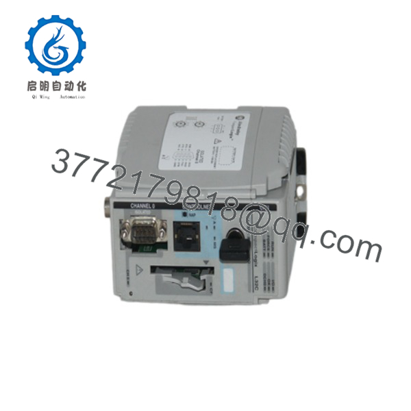
1769-L32C
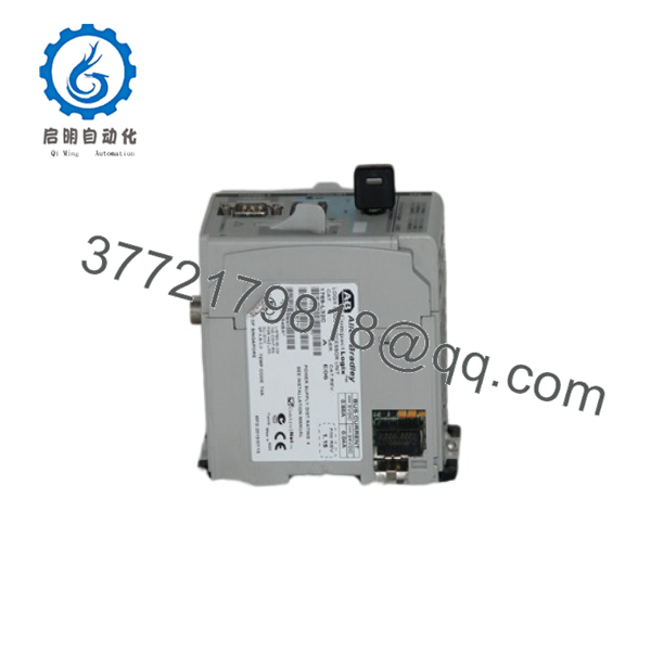
1769-L32C
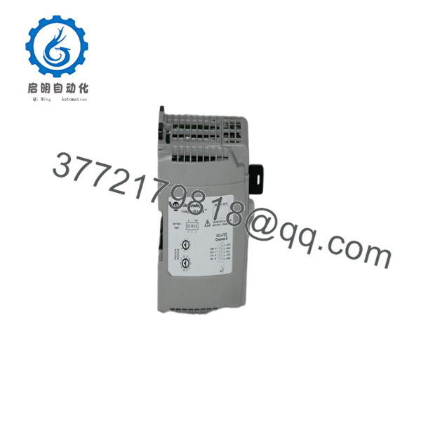
1769-L32C
Installation & Configuration Guide
Stage 1 – Pre-Installation Preparation (5–10 Minutes)
⚠️ Safety First
- Notify plant personnel of scheduled maintenance.
- Perform Lock-Out/Tag-Out procedures.
- Remove system power.
- Verify all status LEDs are OFF.
Required Tools
- ESD wrist strap
- Digital multimeter
- Small Phillips screwdriver
- Ethernet cable (Cat5e or higher)
- Laptop with Studio 5000 Logix Designer
Before Removal
- Upload and back up the controller project.
- Record the firmware revision.
- Save the Ethernet IP configuration.
- Document installed I/O modules and network connections.
Stage 2 – Remove Existing Controller (5 Minutes)
- Verify system power is OFF.
- Disconnect Ethernet cables.
- Remove the SD memory card if installed.
- Release the controller locking mechanism.
- Carefully remove the controller from the Compact I/O assembly.
⚠️ Retain the original controller until the replacement has completed successful commissioning.
Stage 3 – Install the New Controller (10 Minutes)
- Verify the replacement catalog number is 1769-L33ER.
- Install the controller onto the Compact I/O bus.
- Reinstall the SD memory card if required.
- Connect Ethernet cables.
- Download the application program.
- Verify firmware compatibility before switching to RUN mode.
Installation Checklist
- ✔ Correct catalog number
- ✔ Firmware verified
- ✔ Ethernet communication established
- ✔ SD card installed
- ✔ I/O modules detected
Stage 4 – Commissioning & Functional Testing (10–15 Minutes)
- Restore system power.
- Verify the OK, RUN, and NET status LEDs.
- Connect using Studio 5000 Logix Designer.
- Confirm all local and remote I/O modules are online.
- Verify communication with HMIs and drives.
- Test machine operation under normal load.
⚠️ Troubleshooting
- Controller remains in Program mode: verify firmware compatibility.
- Ethernet communication failure: check IP address, subnet mask, and network topology.
- Remote I/O fault: verify EtherNet/IP configuration and adapter status.
- Project download failure: confirm Studio 5000 version matches the controller firmware.
Frequently Asked Questions
Q1. What is the difference between the 1769-L33ER and the 1769-L33ERM?
The is a standard CompactLogix 5370 controller. The 1769-L33ERM adds integrated CIP Motion capability for coordinated servo motion applications. If your application does not require motion control, the is generally sufficient.
Q2. How much memory does the controller provide?
The controller includes 2 MB of user memory and ships with an industrial 1 GB Secure Digital (SD) memory card for application storage and recovery.
Q3. How many local I/O modules can be connected?
The supports up to 16 local 1769 Compact I/O modules, with a maximum of 512 local I/O points, depending on the power budget and system configuration.
Q4. Does the controller require a battery?
No. Unlike older CompactLogix controllers, the uses an internal supercapacitor for memory retention, eliminating the need for routine battery replacement.
Q5. Which programming software is required?
The controller is programmed using Studio 5000 Logix Designer (formerly RSLogix 5000). The installed software version must support the controller’s firmware revision.
Q6. What should I verify before ordering?
Confirm the following:
- Catalog number ()
- Required firmware revision
- Studio 5000 compatibility
- Number of local 1769 I/O modules
- EtherNet/IP network requirements
- Required Ethernet node capacity
- SD memory card requirements
One of the most common startup delays occurs when the Studio 5000 version does not match the controller firmware. Verifying firmware compatibility before downloading the application can significantly reduce commissioning time and avoid unnecessary troubleshooting.



