
 WhatsApp: +86 16626708626
 Email:
  Phone: +86 16626708626
Description
Key Technical Specifications
- Manufacturer: Rockwell Automation / Allen-Bradley
- Catalog Number: 1769-L33ER
- Controller Family: CompactLogix 5370
- User Memory: 2 MB
- Ethernet Ports: 2 × 10/100 Mbps Ethernet
- Ethernet Protocols: EtherNet/IP
- USB Port: 1 × USB programming port
- Local I/O: Compact I/O 1769 series
- Motion Support: Integrated EtherNet/IP motion capability
- Power Supply: 1769 system power supply required; verify rack power budget
- Programming Software: Studio 5000 Logix Designer; exact supported version depends on controller firmware
- Battery: Battery-free controller design
- Mounting: Panel or DIN rail installation
- Operating Temperature: −20 to +60 °C
- Network Topology: Linear, star, and device-level ring architectures where supported by the EtherNet/IP configuration
- Controller Replacement: Verify firmware revision and Studio 5000 compatibility before commissioning
Product Introduction
The Allen-Bradley 1769-L33ER is a CompactLogix 5370 programmable automation controller designed for machine control, process equipment, and distributed I/O applications. It provides 2 MB of user memory, dual Ethernet interfaces, USB programming connectivity, and support for 1769 Compact I/O.
The controller is commonly selected where an existing CompactLogix installation requires EtherNet/IP connectivity and integrated controller-based motion capabilities. For replacement work, the firmware revision, Studio 5000 Logix Designer version, project file, and controller configuration must be checked before installation.
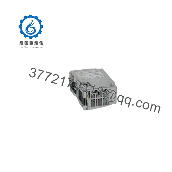
1769-L33ER
Installation & Configuration Guide
Stage 1: Pre-Installation Preparation — Approximately 5–10 Minutes
⚠️ Safety First: Notify operations, place the machine or process in a verified safe state, and apply the site’s lockout/tagout procedure. Isolate the 1769 system power before removing the controller.
Tools Required:
- ESD wrist strap
- PH1 screwdriver
- Calibrated digital multimeter
- Wire labels
- Smartphone or camera
- Laptop with the appropriate Studio 5000 Logix Designer installation
- Current controller project file and applicable firmware files
Data Backup:
- Upload and save the existing controller project if possible.
- Record the controller’s exact catalog number.
- Record the firmware revision.
- Record the controller name and Ethernet configuration.
- Photograph Ethernet connections and all adjacent 1769 modules.
- Document the module order from left to right.
- Record the existing IP address, subnet mask, and gateway.
- Save any applicable Add-On Instructions, UDTs, tags, and device configurations.
⚠️ The firmware revision matters. A Studio 5000 project created for one Logix firmware generation may not open or download directly to a controller running a different major revision.
Stage 2: Removing the Old Controller — Approximately 5 Minutes
- Verify the system is de-energized.
- Disconnect the Ethernet cables and label each port connection.
- Disconnect the USB cable if fitted.
- Release the controller’s retaining mechanism.
- Separate the controller from the adjacent 1769 module without forcing the bus connector.
- Inspect the CompactLogix bus connector and adjacent module for bent contacts, contamination, or mechanical damage.
- Keep the removed controller for configuration and label comparison.
⚠️ Do not pull the controller against an engaged 1769 bus connector. Mechanical damage to the connector can create an intermittent backplane fault that is much harder to diagnose than a failed controller.
Stage 3: Installing the New Controller — Approximately 5–10 Minutes
- Verify the replacement is exactly 1769-L33ER.
- Confirm the hardware revision and label information.
- Put on the grounded ESD strap.
- Align the controller with the 1769 system.
- Engage the controller with the adjacent module connector.
- Confirm the locking mechanism is fully seated.
- Reconnect Ethernet cables to their documented ports.
- Verify the controller’s network configuration before connecting it to the plant network.
Configuration Clone — Critical
Before placing the replacement controller on the production network:
- Connect the programming computer directly or through an isolated engineering network.
- Configure the required IP address.
- Confirm subnet mask and gateway.
- Verify the controller firmware revision.
- Load the correct Studio 5000 project.
- Confirm the controller catalog number shown in the project.
- Verify the 1769 local I/O tree.
- Confirm EtherNet/IP device configurations.
- Review produced/consumed tags where used.
- Review motion axes and associated module configuration.
Self-Checklist:
- 1769-L33ER verified
- Firmware revision verified
- IP address documented
- Ethernet ports identified
- Project backup available
- 1769 I/O tree verified
- Network devices verified
- Controller seated correctly
Stage 4: Power-On & Testing — Approximately 10–15 Minutes
- Check the system wiring before energizing.
- Verify the 1769 power supply has adequate capacity for the complete local I/O assembly.
- Energize the control system.
- Observe the controller status LEDs.
- Connect Studio 5000 Logix Designer.
- Verify that the controller is visible through the engineering connection.
- Confirm the firmware revision.
- Verify the controller’s Ethernet configuration.
- Download the validated project if required.
- Place the controller into the appropriate operating mode.
- Check all local I/O modules.
- Verify EtherNet/IP communications.
- Perform a controlled dry run before returning the machine to automatic production.
⚠️ Do not connect a replacement controller with an unverified IP address to a live plant network. An incorrect address can create an IP conflict and disrupt communications with unrelated EtherNet/IP equipment.
Common Replacement Pitfalls
1. Firmware Revision Mismatch
The 1769-L33ER requires compatibility between controller firmware and the Studio 5000 project. Record the original firmware before removal. Do not assume the replacement controller has the same major revision.
2. Ethernet Configuration
A replacement controller may not automatically contain the old IP configuration. Verify the address, subnet, gateway, and controller network settings before connecting it to the production network.
3. Project Compatibility
Do not simply open an old .ACD file and download it without checking the controller revision and project compatibility. Confirm the exact Logix Designer version and controller firmware first.
4. Local I/O Configuration
The controller can be correct while the local 1769 system is wrong. Check module order, catalog numbers, slot relationships, and configuration parameters.
5. ESD
The controller contains electronic circuitry that can be damaged by static discharge. Use a grounded wrist strap and handle the module by its enclosure. Do not touch connector contacts or PCB circuitry unnecessarily.
Frequently Asked Questions (FAQ)
Can the Allen-Bradley 1769-L33ER be hot-swapped?
Do not treat the 1769- as a generic hot-swappable controller. Controller replacement requires following the applicable CompactLogix installation procedure and the site’s shutdown and electrical-safety requirements. Remove power before physically removing the controller unless the specific system documentation explicitly provides an energized replacement procedure.
Is the 1769- obsolete?
The 1769- belongs to the CompactLogix 5370 generation and should be evaluated against Rockwell Automation’s current lifecycle information before planning a long-term installation. For a production replacement, check the controller’s current lifecycle status and identify the supported migration path rather than assuming a newer CompactLogix controller is a drop-in substitute.
Does the 1769- include Ethernet?
Yes. The controller provides two 10/100 Mbps Ethernet ports for EtherNet/IP networking. Verify the intended topology and network configuration before commissioning the replacement.
Will I lose my PLC program when replacing the 1769-?
The program resides in the controller’s nonvolatile memory rather than being permanently stored in the physical I/O modules. However, do not rely on the replacement controller retaining the original application. Obtain a current Studio 5000 project backup before removing the original controller whenever possible.
Also record the original firmware revision. A project and replacement controller must be compatible before downloading.
Can I use any Studio 5000 version with the 1769-?
No. Studio 5000 Logix Designer compatibility depends on the controller’s firmware revision and project revision. Verify the installed firmware and the project’s major revision before commissioning.
This is one of the easiest ways to turn a 15-minute hardware replacement into several hours of troubleshooting.
Is a New Surplus 1769- the same as a refurbished controller?
No. New Original / New Surplus means the unit has not been represented as refurbished or repaired, although surplus inventory may have been stored outside Rockwell Automation’s current factory distribution channel. Refurbished / Tested indicates that the unit has undergone a repair or testing process.
For a critical spare, request photographs of the actual label, catalog number, hardware revision, serial information, and packaging condition.
What should I verify before ordering a replacement 1769-?
At minimum, provide the supplier with:
- Exact catalog number:
- Controller firmware revision
- Hardware revision
- Existing Studio 5000 project revision
- Current Ethernet configuration
- Local 1769 I/O configuration
- Required condition: New Original / New Surplus or Refurbished / Tested
Do not order only by the family name “CompactLogix 5370.” Different controller catalog numbers have different memory, I/O, communication, and application capabilities.



