
 WhatsApp: +86 16626708626
 Email:
  Phone: +86 16626708626
Description
Key Technical Specifications
| Parameter | Specification |
|---|---|
| Catalog Number | 1769-OW16 |
| Product Family | Allen-Bradley Compact I/O |
| Module Type | Relay Output |
| Number of Outputs | 16 |
| Output Type | Normally open relay contacts |
| Contact Isolation | Individually isolated |
| Operating Voltage | 5–265 V AC; 5–125 V DC |
| Continuous Current | 2.0 A per output |
| Maximum Surge Current | 5 A for 10 ms, repeatable every 2 s |
| Backplane Current | 225 mA @ 5 V DC |
| Minimum Load | 10 mA @ 5 V DC |
| Output Delay | 10 ms maximum, resistive load |
| Off-State Leakage | Essentially zero for relay contacts |
| Mechanical Life | 20 million operations |
| Electrical Life | Application/load dependent |
| Operating Temperature | 0 to 60 °C |
| Storage Temperature | -40 to 85 °C |
| Relative Humidity | 5–95%, noncondensing |
| Terminal Block | Removable |
| Installation | 1769 Compact I/O expansion system |
Product Introduction
The Allen-Bradley 1769-OW16 is a 16-point relay output module for the 1769 Compact I/O platform. Each output uses a relay contact, allowing the module to switch AC or DC loads within its specified voltage and current limits. It is used with CompactLogix and compatible 1769-based controllers for solenoids, contactors, relays, pilot devices, and other discrete loads.
The key distinction is the relay output architecture. Unlike transistor output modules, the 1769-OW16 can switch both AC and DC circuits, but relay contacts have finite mechanical and electrical life. Load type, inrush current, switching frequency, and suppression therefore matter when determining whether this module is appropriate for a particular machine.
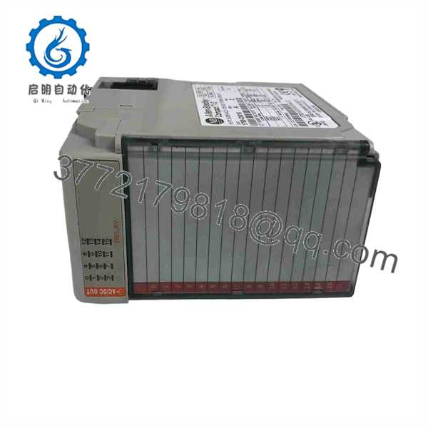
1769-OW16
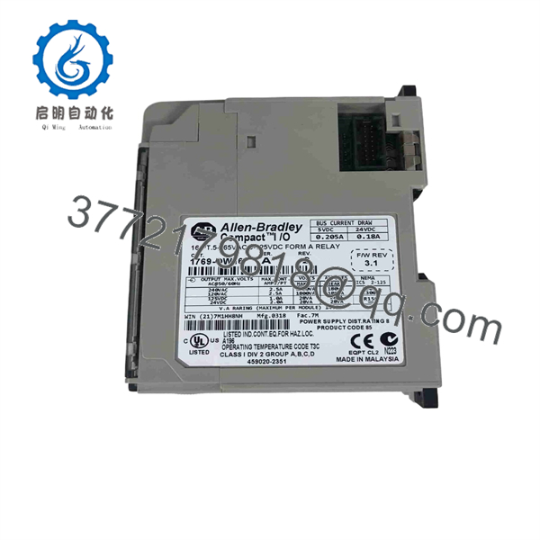
1769-OW16
Installation & Configuration Guide
Stage 1: Pre-Installation Preparation — 10–15 Minutes
⚠️ Safety First: Place the controlled equipment in a safe state and follow the site’s LOTO procedure before disconnecting the module or field wiring.
Tools Required:
- ESD wrist strap
- Phillips screwdriver
- Digital multimeter
- Wire labels
- Smartphone/camera
- Laptop with applicable Rockwell programming software
Data Backup:
- Record the exact 1769-OW16 catalog number and Series.
- Record the module’s physical position in the 1769 I/O assembly.
- Photograph the removable terminal block and all wiring.
- Record the function of every output point.
- Identify the voltage and load type connected to each relay.
- Back up the controller project.
- Pay particular attention to outputs driving contactors, solenoid valves, motors, or other inductive loads.
⚠️ Load warning: A relay’s nominal current rating does not mean every 2 A load is equivalent. A small resistive heater and a contactor coil can impose very different electrical stress on the relay contacts.
Stage 2: Removing the Old Module — 5–10 Minutes
- Confirm the controlled machine is in a safe state.
- Isolate power according to the plant procedure.
- Verify absence of hazardous voltage with an appropriate meter.
- Label every field conductor.
- Photograph the terminal block before disconnecting it.
- Disconnect the wiring without pulling on the conductors.
- Release the 1769-OW16 from the Compact I/O assembly.
- Pull the module straight out.
- Inspect the 1769 bus connector and adjacent modules for damage or contamination.
- Retain the original module until the replacement has passed commissioning.
Stage 3: Installing the New Module — 5–10 Minutes
- Verify the replacement is 1769-OW16.
- Confirm the Series and terminal arrangement.
- Inspect relay-output terminals for damage or contamination.
- Align the module with the 1769 system connector.
- Seat the module completely.
- Reinstall the removable terminal block.
- Reconnect each conductor according to the electrical drawing and photographs.
- Confirm that output commons and external supply circuits are correctly wired.
- Verify protective devices and suppression components on inductive loads.
- Secure the terminal block and module.
Self-Checklist:
- Exact catalog number verified
- Series checked
- Module fully seated
- Terminal block locked
- Output wiring verified
- Load voltage verified
- Suppression checked
- No loose conductors
Stage 4: Power-On & Testing — 15–30 Minutes
- Perform a final wiring inspection.
- Check external output circuits for unintended shorts.
- Restore system power.
- Confirm the controller recognizes the I/O module.
- Verify the module status.
- Test each output individually where the machine’s safety procedure permits.
- Confirm that the commanded output actually switches the intended load.
- Check contactor and solenoid operation.
- Verify that outputs turn off correctly.
- Test relevant interlocks and permissives.
- Confirm HMI indication matches the physical output state.
- Return the equipment to service after the output test is complete.
Common Replacement Pitfalls
❗ 1. Treating Relay Outputs Like Transistor Outputs
The 1769- uses mechanical relay contacts. It is not equivalent to a solid-state DC output module. Relay contact life becomes a design consideration when the output switches frequently.
❗ 2. Ignoring Inductive Loads
Contactor coils and solenoids can generate substantial voltage transients when de-energized. Use the suppression specified for the load and application. Otherwise, repeated switching can shorten relay-contact life.
❗ 3. Exceeding the Contact Rating
The stated 2 A per point rating does not eliminate the need to evaluate inrush current and load category. Check the actual load manufacturer’s electrical specifications.
❗ 4. Assuming All 16 Outputs Share One Supply
The module’s relay contacts provide switching functions rather than acting as a universal power source. Verify the actual wiring architecture and external supply arrangement before energizing the output circuits.
❗ 5. Forgetting the Difference Between AC and DC Switching
The module accommodates both AC and DC within its specified voltage range, but the electrical behavior of relay contacts differs between AC and DC loads. DC arcs are harder to extinguish, making load characteristics especially important.
Frequently Asked Questions (FAQ)
1. What is the Allen-Bradley 1769-?
The is a 16-point relay output module for Allen-Bradley 1769 Compact I/O systems. It provides relay contacts for switching external AC or DC loads within the module’s specified electrical limits.
2. How many outputs does the 1769- have?
It provides 16 relay outputs. The outputs use relay contacts rather than transistor switching devices, which allows AC as well as DC loads to be controlled.
3. What voltage can the 1769- switch?
The specified operating range is 5–265 V AC or 5–125 V DC. The applicable current and load limitations must also be checked; voltage alone does not determine whether a load is suitable.
4. What is the current rating of the 1769-?
The module is rated for 2.0 A per output under its specified conditions. For inductive or high-inrush loads, check the actual load characteristics rather than using 2 A as a universal design limit.
5. Can I hot-swap a 1769-?
Do not assume that it can be hot-swapped. Remove power according to the applicable Rockwell installation procedure and your plant’s LOTO requirements before replacing the module. Removing a 1769 module from an energized assembly can interrupt the I/O bus and affect controller operation.
6. Will replacing the 1769- erase the PLC program?
Replacing the physical I/O module does not normally erase the controller’s user program. However, the controller project contains the module definition and output logic. Back up the project before replacement and verify the I/O configuration after installation.
7. What should I check when buying a surplus 1769-?
Confirm the complete catalog number, Series, physical condition, terminal block condition, relay-output operation, and test status. For a critical spare, a meaningful test should exercise multiple relay outputs under an appropriate load or simulation rather than simply applying power and checking the status indicator.



