
 WhatsApp: +86 16626708626
 Email:
  Phone: +86 16626708626
Description
3. Key Technical Specifications
| Parameter | Value |
|---|---|
| Inputs per Module | 8 |
| Input Voltage Range | 10 to 27 V DC |
| Nominal Input Current | 8 mA @ 12 V DC; 24 mA @ 24 V DC |
| Max Off-State Current | 3.0 mA |
| Max Off-State Voltage | 7.0 V DC |
| Min On-State Voltage | 10 V DC |
| Input Signal Delay (On) | 12 ms + 7 ms |
| Input Signal Delay (Off) | 20 ms + 7 ms |
| Backplane Current | 74 mA @ 5 V DC ±5% |
| Isolation Voltage | 1500 V AC rms |
| Power Dissipation | 5.7 W max; 0.4 W min |
| Operating Temperature | 0 to 60 °C (32 to 140 °F) |
| Storage Temperature | –40 to 85 °C |
| Field Wiring Arm | 1771-WA |
| Keying Bands | 4–6 and 14–16 |
4. Product Introduction
The Allen-Bradley 1771-IB is an 8-point DC digital input module for the PLC-5 and 1771 I/O chassis family. It converts 10–27 V DC signals from source-switching field devices (proximity switches, pushbuttons, limit switches, photoelectric sensors) into logic levels the processor can read.
It draws only 74 mA from the backplane, provides 1500 V optical isolation, and includes front-panel status LEDs plus a removable 1771-WA wiring arm. Direct drop-in replacement for existing 1771-IB modules in local or remote 1771 chassis. Common choice for brownfield PLC-5 systems still running discrete DC inputs.
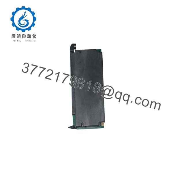
1771-IB
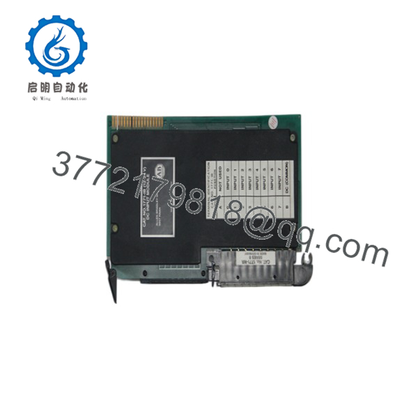
1771-IB
5. Troubleshooting Quick Reference
| Symptom | Possible Cause | Relevance to this Part | Quick Check Method | Recommendation |
|---|---|---|---|---|
| No LEDs on module | Chassis power supply failure or missing 5 V | ❌ Low | Measure 5 V at backplane; check chassis PSU | Verify chassis power before replacing module |
| All input LEDs stay off | Field power missing or wiring open | ❌ Low | Measure 10–27 V DC at input terminals relative to common | Check field supply and wiring first |
| Single input LED stays off while field device is on | Open field wire, failed sensor, or input circuit fault | ✅ High | Force field device ON; measure voltage at terminal vs common | If voltage present but LED off, module channel likely failed |
| Input LED on but PLC data table bit remains 0 | Addressing mismatch or module not scanned | ✅ Medium | Verify slot addressing (1/2, 1, or 2-slot) and I/O configuration | Confirm chassis keying and processor I/O map |
| Intermittent input status | Contact bounce, noise, or marginal voltage | ✅ Medium | Scope input signal; confirm voltage stays above 10 V | Check filtering (12/20 ms delay is normal); clean connections |
| Module works after reseat but fails later | Edge connector oxidation or poor keying | ✅ High | Inspect gold fingers and keying bands | Clean contacts; confirm keying bands at 4-6 and 14-16 |
If the above checks do not resolve the issue, send clear photos of the module face, wiring arm, and diagnostic buffer screenshot. Contact technical support with the exact series letter and any fault codes.
6. Frequently Asked Questions (FAQ)
Q: Is the 1771-IB still in production? No. The PLC-5 / 1771 platform is discontinued. Current stock is New Surplus or tested refurbished. Lead times and availability vary; confirm current inventory before ordering.
Q: Can I hot-swap this module? No. Power down the chassis before inserting or removing the 1771-IB. Hot-swapping risks backplane damage and can corrupt I/O data.
Q: What wiring arm does it use? 1771-WA. Keep the original wiring arm when possible so field wires stay connected during a module swap.
Q: Will a 1771-IBD or 1771-IBN work as a direct replacement? No. The 1771-IB is 8 points, 10–27 V. The IBD is 16 points and the IBN is 32 points with different current draw, keying, and addressing. Use only another 1771-IB for a one-for-one swap.
Q: Does the module retain any configuration when powered down? No configuration is stored on the 1771-IB itself. Addressing is set by the chassis keying bands and the processor’s I/O configuration table. Always photograph the keying bands before removal.
Q: Why is the price lower than a new factory module? Because the platform is obsolete. Units offered as New Surplus or fully tested refurbished carry a 1-year warranty and are verified on a live 1771 chassis. Factory-new production units are no longer available.
Q: What is the maximum off-state leakage I can tolerate from a 3-wire sensor? 3.0 mA. Exceeding this can cause false ON states. Verify sensor leakage current against the module specification before installation.



