
 WhatsApp: +86 16626708626
 Email:
  Phone: +86 16626708626
Description
Key Technical Specifications
| Parameter | Value |
|---|---|
| Product Type | Analog Input Module |
| Series | 1771 PLC-5 I/O |
| Input Channels | 16 Single-Ended or 8 Differential (Selectable) |
| Input Signal Types | Voltage and Current |
| Voltage Ranges | 0–5 V, 1–5 V, ±5 V, ±10 V |
| Current Ranges | 4–20 mA, 0–20 mA, ±20 mA |
| Resolution | 12-bit (+ Sign on Bipolar Ranges) |
| Data Format | Natural Binary or BCD (Scaled to ±9999) |
| Channel Update Time | 18 ms (8 Differential), 36 ms (16 Single-Ended) |
| Backplane Current | 750 mA |
| External Power Required | No |
| Wiring Arm | 1771-WG |
| Mounting | 1771 I/O Chassis |
| Operating Method | Block Transfer |
The 1771-IFE is a PLC-5 analog input module that supports 16 single-ended or 8 differential analog inputs. It accepts both voltage and current signals, including 0–5 V, 1–5 V, ±5 V, ±10 V, 4–20 mA, 0–20 mA, and ±20 mA, using 12-bit resolution and block-transfer communication with the PLC processor.
Product Introduction
The Allen-Bradley 1771-IFE is an analog input module developed for the PLC-5 and 1771 I/O platform. It converts analog signals from field instruments into digital values that can be processed by the controller for monitoring, regulation, alarming, and closed-loop control.
The module supports either 16 single-ended channels or 8 differential channels, allowing engineers to balance channel density with improved noise immunity. Individual channels can be configured for various voltage or current ranges, making the module suitable for pressure transmitters, flow meters, temperature transmitters, level sensors, load cells with signal conditioners, and other industrial instrumentation.
Unlike standard discrete I/O modules, the 1771-IFE exchanges configuration and process data through block-transfer instructions, providing flexible scaling, engineering unit conversion, filtering, and diagnostic capabilities. It can be installed in any compatible 1771 I/O chassis that supports block-transfer communication.
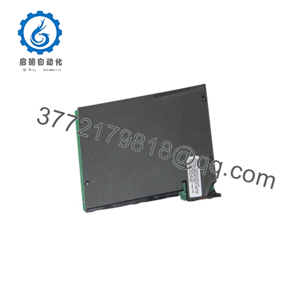
1771-IFE
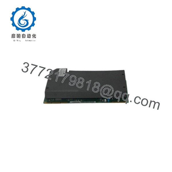
1771-IFE
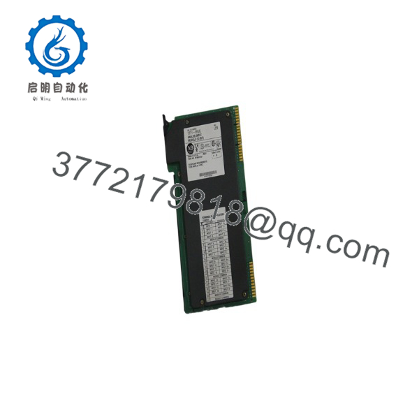
1771-IFE
Installation & Configuration Guide
Stage 1 – Pre-Installation Preparation (5–10 Minutes)
⚠️ Safety First
- Notify plant personnel before maintenance.
- Follow Lock-Out/Tag-Out procedures.
- Remove chassis power.
- Verify all analog loops are in a safe condition.
Required Tools
- ESD wrist strap
- Digital multimeter
- Small screwdriver
- Shielded analog signal cable
- PLC programming software
Before Removal
- Upload the PLC program.
- Record the Block Transfer Write (BTW) configuration.
- Document channel scaling.
- Label all field wiring.
- Photograph terminal connections.
Stage 2 – Remove Existing Module
- Confirm chassis power is OFF.
- Disconnect the 1771-WG wiring arm.
- Remove the module from the chassis.
- Inspect the backplane connector.
- Verify the wiring arm condition.
⚠️ Never remove the module while the chassis is energized.
Stage 3 – Install the Replacement Module
- Confirm the replacement catalog number is 1771-IFE.
- Configure jumpers for single-ended or differential operation as required.
- Install the module into the selected slot.
- Reconnect the 1771-WG wiring arm.
- Restore the Block Transfer configuration.
- Verify input ranges for every channel.
Installation Checklist
- ✔ Correct catalog number
- ✔ Jumper configuration verified
- ✔ Input ranges configured
- ✔ Wiring arm securely installed
- ✔ Block Transfer configuration restored
Stage 4 – Commissioning & Functional Testing
- Restore chassis power.
- Verify module status.
- Execute the Block Transfer Write configuration.
- Read analog values through Block Transfer Read.
- Verify engineering-unit scaling.
- Compare readings against calibrated field instruments.
⚠️ Troubleshooting
- No analog values: verify Block Transfer configuration.
- Incorrect scaling: inspect engineering-unit settings.
- Unstable readings: check shielding, grounding, and differential wiring.
- Communication fault: verify chassis addressing and PLC-5 compatibility.
Frequently Asked Questions
Q1. How many analog inputs does the 1771-IFE support?
The module can be configured for either 16 single-ended inputs or 8 differential inputs, depending on the application and jumper settings.
Q2. What analog signals are supported?
Supported signal ranges include:
- 0–5 VDC
- 1–5 VDC
- ±5 VDC
- ±10 VDC
- 4–20 mA
- 0–20 mA
- ±20 mA
These ranges can be configured on a per-channel basis.
Q3. Does the module require an external power supply?
No. The 1771-IFE receives operating power directly from the 1771 I/O backplane and does not require a separate external power supply.
Q4. How does the PLC communicate with the module?
The module uses Block Transfer Write (BTW) instructions for configuration and Block Transfer Read (BTR) instructions for transferring analog input data between the module and the PLC processor.
Q5. Which wiring arm is required?
The recommended field wiring arm for the 1771-IFE is the 1771-WG, which provides the required field wiring connections for the module.
Q6. What should I verify before ordering?
Confirm the following:
- Catalog number (1771-IFE)
- PLC-5 / 1771 I/O chassis compatibility
- Required channel configuration (16 single-ended or 8 differential)
- Voltage or current input requirements
- Block Transfer programming support
- Required 1771-WG wiring arm
- Available chassis slot
- Analog signal scaling requirements
One of the most common issues during PLC-5 upgrades is failing to restore the original Block Transfer Write (BTW) configuration after replacing the module. Before commissioning, verify the configured input ranges, scaling parameters, and engineering-unit conversion values to ensure the new module produces measurements consistent with the original installation.



