
 WhatsApp: +86 16626708626
 Email:
  Phone: +86 16626708626
Description
Key Technical Specifications
| Parameter | Value |
|---|---|
| Product Type | Digital DC Output Module |
| Series | 1771 PLC-5 I/O |
| Number of Outputs | 32 |
| Output Configuration | High-True (Sourcing) |
| Output Groups | 4 Groups of 8 Outputs |
| Operating Voltage | 10–30 VDC |
| Maximum Output Current | 0.5 A per output |
| Maximum Group Current | 2 A per group |
| Maximum Module Current | 8 A |
| Surge Current | 2 A per output (10 ms) |
| Output Delay | OFF→ON: 0.1 ms / ON→OFF: 2.0 ms |
| Backplane Current | 330 mA @ 5 VDC |
| Isolation Voltage | 1500 VAC RMS |
| Wiring Arm | 1771-WN |
| Mounting | 1771 I/O Chassis |
The 1771-OBN is a 32-point DC digital output module for the PLC-5 1771 I/O platform. It provides 32 sourcing (high-true) outputs arranged in four groups of eight, operating from 10–30 VDC with a maximum output current of 0.5 A per channel and 8 A per module.
Product Introduction
The Allen-Bradley 1771-OBN is a high-density discrete output module designed for PLC-5 and 1771 Universal I/O systems. It converts controller output commands into 10–30 VDC switching signals for industrial field devices, making it suitable for machine automation, process control, and OEM equipment.
With 32 sourcing outputs, the module efficiently controls DC loads such as solenoid valves, relay coils, contactors, indicator lamps, annunciators, and other industrial actuators while minimizing rack space requirements. The outputs are divided into four independently fused groups, helping isolate faults and simplify maintenance.
The module installs in any compatible 1771 I/O chassis and connects to field wiring through the 1771-WN wiring arm. Diagnostic LEDs indicate the status of each output channel, while a fuse indicator identifies blown group fuses for faster troubleshooting.
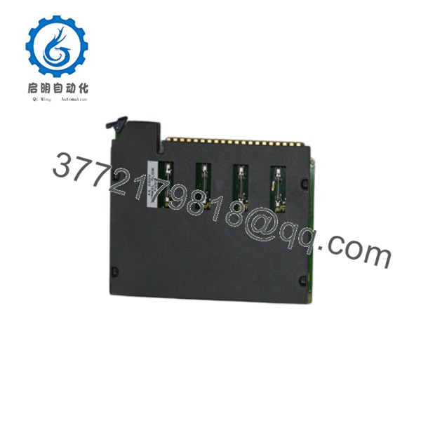
1771-OBN
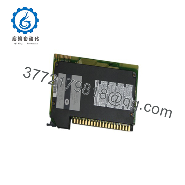
1771-OBN
Installation & Configuration Guide
Stage 1 – Pre-Installation Preparation
⚠️ Safety Requirements
- Follow Lock-Out/Tag-Out procedures.
- Remove power from the PLC chassis and field circuits.
- Verify all connected loads are de-energized.
- Wear appropriate ESD protection.
Before Removal
- Back up the PLC-5 program.
- Record the module slot location.
- Label all field wiring.
- Verify field supply voltage (10–30 VDC).
- Inspect replacement module and wiring arm.
Stage 2 – Remove the Existing Module
- Turn OFF chassis power.
- Disconnect the 1771-WN wiring arm.
- Release the module retaining latch.
- Remove the module from the chassis.
- Inspect the backplane connector and wiring arm for damage.
Important: Never insert or remove the module while chassis power is applied.
Stage 3 – Install the Replacement Module
- Verify the replacement part number is 1771-OBN.
- Set the chassis keying according to the installation manual.
- Insert the module into the selected slot.
- Reattach the 1771-WN wiring arm.
- Connect field wiring and verify group commons.
- Check the four output-group fuses.
Installation Checklist
- ✔ Correct catalog number verified
- ✔ Wiring arm securely installed
- ✔ Field voltage confirmed
- ✔ Output group wiring verified
- ✔ Fuses inspected
- ✔ Module fully seated
Stage 4 – Commissioning
- Restore chassis power.
- Verify the module status indicators.
- Test each output channel individually.
- Confirm proper operation of all connected field devices.
- Monitor module temperature and output loading during initial operation.
Common Troubleshooting
- No outputs operating: Verify field power supply and chassis power.
- One output group inactive: Inspect the corresponding fuse.
- Individual output failure: Check field wiring and connected load.
- Excessive heating: Verify that per-channel, per-group, and total module current ratings are not exceeded.
Frequently Asked Questions
Q1. Is the 1771-OBN a sourcing or sinking output module?
The 1771-OBN provides high-true (sourcing) DC outputs that supply positive voltage to compatible sinking field devices.
Q2. How many outputs does the module provide?
The module provides 32 digital outputs, organized into four groups of eight channels.
Q3. What output voltage does the 1771-OBN support?
The module operates with 10–30 VDC field power and is intended for industrial DC control circuits.
Q4. What is the maximum output current?
Each output can switch up to 0.5 A, with a maximum of 2 A per output group and 8 A for the entire module.
Q5. Which wiring arm is required?
The recommended wiring arm is the 1771-WN, designed specifically for the 1771-OBN output module.
Q6. What should I verify before ordering?
Confirm the following:
- Catalog number (1771-OBN)
- PLC-5 / 1771 I/O chassis compatibility
- Required output type (sourcing/high-true)
- Field supply voltage (10–30 VDC)
- Total output current requirements
- Availability of the 1771-WN wiring arm
- Output group fuse condition
- Available chassis slot
A frequent cause of output failures is exceeding the 2 A limit per output group or overlooking a blown group fuse. Before replacing the module, verify the load distribution across all four output groups and confirm that the connected devices remain within the specified current ratings.



