
 WhatsApp: +86 16626708626
 Email:
  Phone: +86 16626708626
Description
Key Technical Specifications
| Parameter | Value |
| Catalog Number | 1771-OW16 |
| Number of Outputs | 16 electromechanical relay contacts |
| Contact Configuration | 8 Normally Open (N.O.), 8 Selectable (N.O. or N.C.) |
| Operating Voltage Range | 24–250 VAC (47–63 Hz) / 24–150 VDC |
| Maximum Current Rating | 2.0 A per output at rated power |
| Maximum Power Rating | 500 VA per output (AC) / 80 W per output (DC) |
| Minimum Contact Load | 10 mA |
| Operate / Release Time | 10 ms maximum (5 ms typical) |
| Backplane Current Load | 1.3 A at 5 VDC (1300 mA) |
| Isolation Rating | 1500 VAC continuous (channel-to-channel and channel-to-system) |
| Backplane Keying | Between pins 2 and 4, and pins 32 and 34 |
| Field Wiring Arm | 1771-WN (40-pin terminal arm) |
Product Introduction & Supply Chain Strategy
The Allen-Bradley 1771-OW16 provides 16 individually isolated electromechanical relay outputs designed for PLC-5 control systems. It directly drives external loads such as solenoid valves, motor starters, and interlocks across a broad voltage spectrum of 24–250 VAC or 24–150 VDC.
Since Rockwell Automation officially designated the 1771 product line as End-of-Life (EOL), plant engineers face supply chain risks when replacing failed output modules. Sourcing verified New Surplus units preserves factory reliability, avoiding worn contacts, welded relay tips, and board-level degradation common in refurbished parts. Maintaining critical spare units on-site prevents costly emergency line stops while protecting overall plant Total Cost of Ownership (TCO).
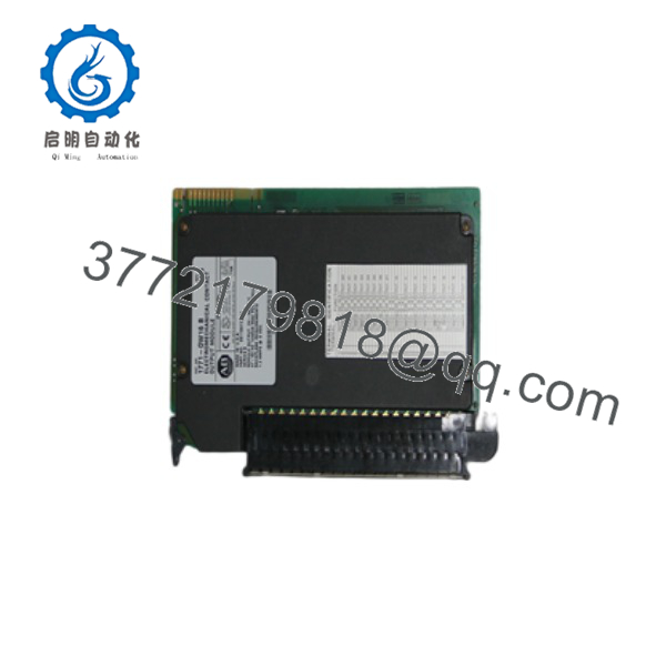
1771-OW16
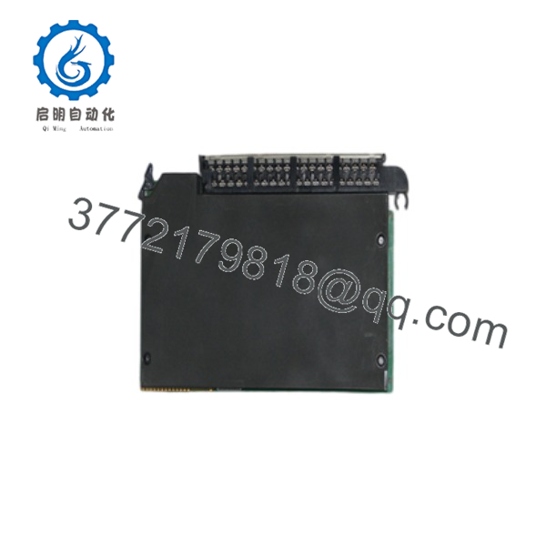
1771-OW16
Installation & Configuration Guide
Stage 1: Pre-Installation (Prep & Safety)
- Lock-Out/Tag-Out (LOTO): De-energize all 120/240 VAC or DC field power supplies connected to the 1771-WN wiring arm before handling.
- ESD Protection: Attach a grounded anti-static wrist strap to prevent electrostatic damage to backplane logic components.
- Configuration Check: Set the internal jumpers on channels 10 through 17 for Normally Open (N.O.) or Normally Closed (N.C.) operation prior to rack insertion. Record DIP switch and keying positions.
Stage 2: Removal
- Unlatch the upper and lower chassis retaining clips on the existing card slot.
- Disengage the 1771-WN field wiring arm by pulling the locking tab and pivoting it away from the module face.
- Pull the old module straight out along the chassis guide rails to protect the rear edge connectors.
Stage 3: Installation (Clone & Seat)
- Confirm that backplane plastic keying bands match positions 2/4 and 32/34.
- Slide the 1771-OW16 into the slot card guides until the rear connector fully seats into the backplane bus.
- Secure the module top and bottom latches, then snap the 1771-WN wiring arm firmly onto the front connector.
Stage 4: Power-On & Testing
- Measure incoming field voltages on the wiring arm terminals with a digital multimeter to confirm ratings fall within 24–250 VAC or 24–150 VDC.
- Apply backplane logic power; ensure the front panel status LEDs light up when individual relay coils energize during PLC logic tests.
- Verify mechanical relay contact switching on each active channel before returning the system to full automatic operation.
Firmware/Software Versions & Upgrade Notes
- Hardware Architecture: The 1771-OW16 functions as a passive hardware relay interface and does not run flashable module firmware.
- Controller Compatibility: Fully supported across all standard PLC-5 processors (such as PLC-5/11, PLC-5/20, PLC-5/40, and PLC-5/80) using RSLogix 5 programming software.
- Addressing Parameters: Ensure 1/2-slot, 1-slot, or 2-slot addressing DIP switches on the 1771 chassis backplane correctly match the 16-point output allocation. Misconfigured addressing causes I/O bit overlaps and improper contact actuation.
Frequently Asked Questions (FAQ)
Is this unit guaranteed to be New Surplus and not refurbished?
Yes. This module is 100% Brand New Surplus stock in original OEM condition. It has never been installed in an active control panel, refurbished, or modified with aftermarket relay components.
Why should I choose New Surplus over refurbished 1771-OW16 modules?
Electromechanical relays suffer mechanical wear and contact oxidation over time. Refurbished modules often carry hidden contact pitting that causes intermittent open-circuits or high-resistance voltage drops. New Surplus guarantees 300,000 operations at full rated load and zero pre-existing electrical fatigue.
How do I configure channels 10–17 between Normally Open and Normally Closed?
Channels 0–7 are fixed as Normally Open (N.O.). Channels 10–17 feature internal selection jumpers on the printed circuit board. Position these jumpers according to your schematic requirements before seating the module into the chassis backplane.
Can I insert or remove the 1771-OW16 while the chassis power is on?
No. Standard 1771 I/O chassis do not support Removal and Insertion Under Power (RIUP). Always disconnect 5 VDC chassis backplane power and field wiring power before inserting or pulling any module to avoid backplane arcing or CPU faulting.
Do I need external surge protection for inductive loads?
Yes. The 1771- does not contain internal surge suppression networks. When switching inductive loads like solenoid coils or contactor coils, install external RC networks (for AC loads) or flyback diodes (for DC loads) directly across the field device terminals to prolong relay contact life.



