
 WhatsApp: +86 16626708626
 Email:
  Phone: +86 16626708626
Description
3. Key Technical Specifications
| Parameter | Value |
|---|---|
| Module Type | Communication Interface Module |
| Mounting | Single slot in 1771 I/O chassis |
| Communication Ports | DH+ (3-screw terminal); RS-232-C (15-pin female D-shell); 1784-T50 (9-pin male) |
| DH+ Data Rate | Up to 57,600 bps |
| RS-232-C Data Rate | Switch-selectable 110 to 19,200 bps |
| Protocol Options | Full-duplex or half-duplex |
| Backplane Current | 1.2 A @ 5 V DC |
| Max Modules per System | 4 |
| Compatible Controllers | PLC-2, PLC-3, PLC-4, PLC-5 |
| Operating Temperature | 0 to 60 °C (32 to 140 °F) |
| Storage Temperature | –40 to 85 °C (–40 to 185 °F) |
| Relative Humidity | 5 to 95 % non-condensing |
| Wiring Arm | 1771-WN |
| Dimensions (approx.) | 115 × 317 × 160 mm (4.5 × 12.4 × 6.3 in) |
| Weight (approx.) | 0.1–0.8 kg depending on source listing |
4. Product Introduction
The Allen-Bradley 1785-KE is a single-slot Data Highway Plus communication interface module that bridges an intelligent RS-232-C device to a DH+ network. It mounts in a 1771 I/O chassis and draws 1.2 A at 5 V DC from the backplane.
The module supports both full-duplex and half-duplex protocols on the asynchronous RS-232 link and provides a fixed 57.6 kbps DH+ connection. Configuration is performed via onboard DIP switches for node address, baud rates, parity, and protocol options. It is commonly used to connect serial devices, modems, or programming terminals to existing DH+ networks in PLC-5 systems.
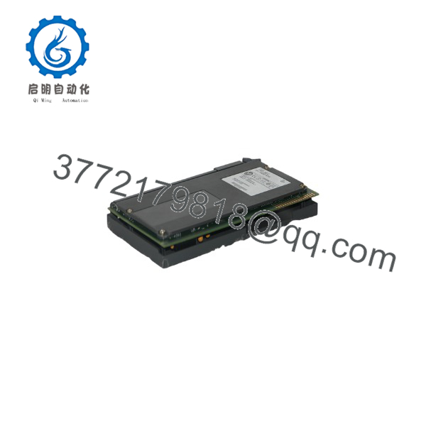
1785-KE
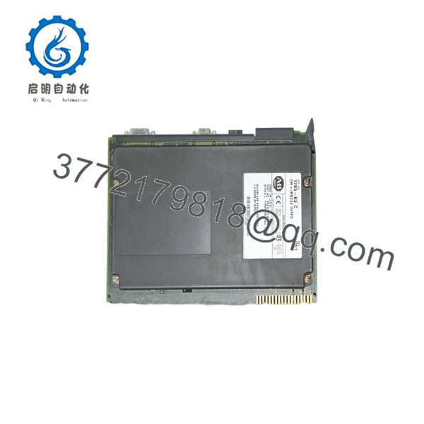
1785-KE
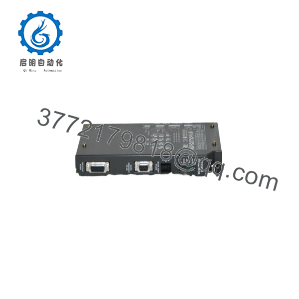
1785-KE
5. Installation & Configuration Guide
Stage 1: Pre-Installation Preparation (5–10 min) ⚠️ Safety First: Place the system in a safe state. Lock out/tag out chassis power. Wait for residual voltage to dissipate. Wear an ESD wrist strap. Tools Required: ESD strap, PH1 screwdriver, multimeter, smartphone for photos of switch settings. Data Backup: Photograph all DIP switch positions on the existing module. Record the current DH+ node address and RS-232 parameters. Note the total chassis current draw.
Stage 2: Removing the Old Module (5–8 min)
- Confirm chassis power is removed.
- Disconnect the DH+ trunk/drop cable from the 3-screw terminal and the RS-232 cable from the 15-pin connector. Label both.
- Release the module locking tab and pull the module straight out of the chassis.
- Inspect the backplane connector for bent pins or debris. ⚠️ Retain the old module until the replacement is fully tested.
Stage 3: Installing the New Module (10–15 min)
- Verify the module is marked 1785-KE. Set the DIP switches (SW1–SW4) to match the photographed settings or the required node address, baud rates, and protocol (full- or half-duplex).
- Align the module with the chassis guides and slide it fully into the slot until it seats firmly.
- Reconnect the DH+ cable (Belden 9463 or equivalent) to the 3-screw terminal and the RS-232 cable (1770-CG or 1770-CP) to the 15-pin connector.
- Secure the module locking tab. Self-Checklist: [ ] DIP switches match required configuration [ ] Module fully seated [ ] Cables secure and correctly polarized.
Stage 4: Power-On & Testing (10–20 min)
- Apply chassis power. Observe the status LEDs for each channel.
- Verify the module appears on the DH+ network at the configured node address using RSLinx or equivalent.
- Test RS-232 communication with the attached device (full- or half-duplex as configured).
- Confirm message traffic and error-free operation under normal load. ⚠️ Troubleshooting Note: No communication is most often caused by incorrect node address, mismatched baud rate/parity, or reversed RS-232 wiring. After any switch change, cycle power to the module.
6. Frequently Asked Questions (FAQ)
Q: Can the 1785-KE be hot-swapped? No. Always remove chassis power before inserting or removing the module. Hot-swapping can damage the backplane or the module.
Q: Is the 1785-KE still in production? No. The PLC-5 / 1771 family, including the 1785-KE, is discontinued. Remaining units are new surplus or refurbished. Plan migration to ControlLogix DH+ modules (1756-DHRIO) or Ethernet-based solutions when feasible.
Q: What is the maximum number of 1785-KE modules per system? Four modules can be used in a single system.
Q: Does the module communicate through the 1771 backplane? No. The 1785-KE does not exchange data with the processor through the backplane. It operates as a standalone network interface on the DH+ and RS-232 ports.
Q: Why is the price lower than historical OEM list price? These are genuine surplus units from excess inventory. They are original Allen-Bradley modules that have never been installed, but they are no longer available through standard Rockwell channels. Functional testing and warranty coverage are provided.
Q: What cables are required? DH+: Belden 9463 (or equivalent drop-line cable) to the 3-screw terminal. RS-232: 1770-CG (data terminal) or 1770-CP (modem) cable to the 15-pin connector.
Q: Can I use this module with modern Windows systems? Yes for basic messaging via RSLinx Classic, but verify driver and OS compatibility. Many modern 64-bit systems require legacy support or virtualization for reliable serial/DH+ operation.



