
 WhatsApp: +86 16626708626
 Email:
  Phone: +86 16626708626
Description
3. Key Technical Specifications
| Parameter | Value |
|---|---|
| I/O Capacity | 8 FLEX I/O modules |
| Communication Rate | 5 Mbps |
| ControlNet Ports | Dual BNC (Channel A and Channel B) for redundant media |
| Network Access Port | 1 NAP (RJ-45 style) |
| Input Voltage | 19.2–31.2 V DC (24 V DC nominal), 400 mA |
| Flexbus Output | 5 V DC, 640 mA max |
| Inrush Current | 14 A for 2 ms |
| Power Dissipation | 3.4 W max @ 19.2 V DC |
| Isolation Voltage | 50 V continuous (basic insulation); tested to 860 V AC for 60 s |
| Node Address | Thumbwheel switches |
| Operating Temperature | –25 to +55 °C (–13 to +131 °F) |
| Storage Temperature | –40 to +85 °C (–40 to +185 °F) |
| Relative Humidity | 5 to 95 % non-condensing |
| Dimensions (approx. H × W × D) | 87 × 94 × 69–92 mm (3.4 × 3.7 × 2.7–3.6 in) |
| Weight | Approx. 220 g (7.76 oz) |
| Mounting | DIN rail |
4. Product Introduction
The Allen-Bradley 1794-ACNR15 is a FLEX I/O ControlNet adapter with redundant media capability. It connects up to eight FLEX I/O modules to a ControlNet network and provides dual BNC connectors (Channel A and Channel B) for media redundancy. When both channels are connected, the adapter automatically routes traffic if one trunk fails.
The module includes a built-in power supply that converts the external 24 V DC input to 5 V DC for the Flexbus. It supports Removal and Insertion Under Power (RIUP) for the I/O modules, node address selection via thumbwheel switches, and a Network Access Port for programming. The 1794-ACNR15 can also serve as a functional replacement for the single-channel 1794-ACN15 when only Channel A is used.
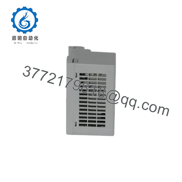
1794-ACNR15
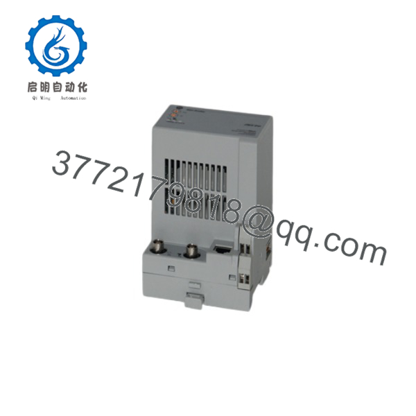
1794-ACNR15
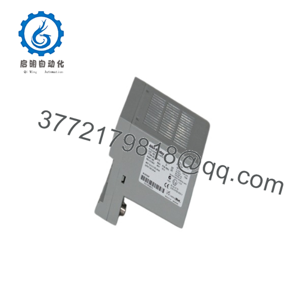
1794-ACNR15
5. Installation & Configuration Guide
Stage 1: Pre-Installation Preparation (5–10 min) ⚠️ Safety First: Place the system in a safe state. Lock out/tag out the 24 V DC supply and any field power. Wear an ESD wrist strap. Tools Required: ESD strap, screwdriver, multimeter, smartphone for photos of switch settings and cabling. Data Backup: Record the current node address (thumbwheel settings), ControlNet schedule, and I/O configuration in RSNetWorx for ControlNet. Photograph all connections.
Stage 2: Removing the Old Adapter (5–8 min)
- Confirm power is removed from the adapter.
- Disconnect the ControlNet BNC cables (and NAP cable if present). Label Channel A and Channel B.
- Disconnect the 24 V DC power wires.
- Release the locking tab and slide the adapter off the DIN rail / terminal base. ⚠️ Keep the old adapter until the replacement is fully tested.
Stage 3: Installing the New Adapter (8–12 min)
- Verify the module is marked 1794-ACNR15. Set the thumbwheel switches to the required ControlNet node address.
- Mount the adapter on the DIN rail or terminal base and lock it in place.
- Connect the 24 V DC supply (observe polarity).
- Connect ControlNet media: Channel A is primary; Channel B is used only for redundant media. Use Belden RG-6/U or equivalent.
- Connect the NAP cable if required for local programming. Self-Checklist: [ ] Node address set correctly [ ] Power polarity correct [ ] Channel A connected [ ] Module locked firmly.
Stage 4: Power-On & Testing (10–20 min)
- Apply 24 V DC power. Observe the I/O Status, Comm A, and Comm B LEDs.
- Verify the adapter appears on the ControlNet network at the configured node address using RSNetWorx or RSLinx.
- Confirm all eight possible FLEX I/O modules are recognized and data is exchanging.
- If redundant media is used, test failover by disconnecting one channel. ⚠️ Troubleshooting Note: Solid red Comm LED usually indicates a media or node-address conflict. Flashing green indicates online but not scheduled. Always match the node address and schedule from the original configuration.
6. Frequently Asked Questions (FAQ)
Q: Can the 1794-ACNR15 be hot-swapped? No. Always remove the 24 V DC power before inserting or removing the adapter. FLEX I/O modules themselves support Removal and Insertion Under Power, but the adapter does not.
Q: Is the 1794-ACNR15 still in production? No. The FLEX I/O ControlNet adapters are discontinued. Remaining units are new surplus or refurbished. For new designs, migrate to EtherNet/IP FLEX I/O adapters (1794-AENT or 1794-AENTR).
Q: Can I use this as a direct replacement for a 1794-ACN15? Yes. Connect the existing ControlNet cable to Channel A only. The module will function as a single-channel adapter. Channel B can be left unused or used later for media redundancy.
Q: How many FLEX I/O modules can be attached? A maximum of eight modules of any mix (digital, analog, specialty).
Q: Why is the price lower than historical OEM list price? These are genuine surplus units from excess inventory. They are original Allen-Bradley modules that have never been installed in a running system, but they are no longer available through standard Rockwell channels. Functional testing and warranty are provided.
Q: What cable is required for ControlNet? Belden RG-6/U (or Allen-Bradley 1786-RG6 / 1786-RG6F high-flex). Use proper BNC connectors and terminators at the ends of each trunk.
Q: Does the adapter supply power to the I/O modules? Yes. It converts the external 24 V DC input to 5 V DC (up to 640 mA) on the Flexbus for the attached modules.



