
 WhatsApp: +86 16626708626
 Email:
 Phone: +86 16626708626
Description
Core Product Summary (Brand / Model / Key Attributes)
The Allen-Bradley 1794-IE8XOE4 is a high-density analog combination module belonging to the FLEX I/O industrial distributed automation ecosystem. Designed to consolidate analog signal acquisition and output control into a single slot, this module provides 8 single-ended analog inputs and 4 single-ended analog outputs. It is used across distributed control architectures to monitor process variables—such as pressure, temperature, and flow transmitters—while simultaneously driving control elements such as control valves, drives, and positioners.
Operating on an external 24V DC field supply (19.2 to 31.2V DC window), the 1794-IE8XOE4 converts signals using a 16-bit successive approximation resolution across user-configurable 0 to 20 mA, 4 to 20 mA, 0 to 10V, or ±10V ranges. The module mounts directly onto a standard 1794 terminal base unit (such as the 1794-TB3 or 1794-TB3S), which routes field wiring and backplane signals. It also features Removal and Insertion Under Power (RIUP) capability, enabling online module replacement without interrupting system field wiring or communication to adjacent I/O modules on the FLEX I/O rail.
Key Technical Specifications
| Specification Parameter | Verified Value / Range |
|---|---|
| Manufacturer / Brand | Allen-Bradley / Rockwell Automation |
| Catalog / Order Number | 1794-IE8XOE4 |
| Product Series | FLEX I/O Analog Combination Module |
| Number of Channels | 12 Channels Total (8 Inputs / 4 Outputs) |
| Input Signal Types | Single-ended, non-isolated (0…20 mA, 4…20 mA, 0…10V, ±10V) |
| Output Signal Types | Single-ended, non-isolated (0…20 mA, 4…20 mA, 0…10V, ±10V) |
| Conversion Resolution | 16-bit resolution (Voltage: approx. 320 µV/cnt; Current: approx. 0.641 µA/cnt) |
| Conversion Method | Successive approximation |
| External Field Power Supply | 24V DC nominal (19.2 to 31.2V DC, includes 5% AC ripple) |
| FLEXbus Current Draw | 80 mA @ 5V DC |
| Maximum Power Dissipation | 3.0 W @ 31.2V DC |
| Thermal Dissipation | 10.2 BTU/hr @ 31.2V DC |
| Absolute Accuracy | 0.1% Full Scale @ 25°C (voltage and current terminals) |
| Isolation Voltage | 50V continuous (basic insulation type), field-side to system-side |
| Compatible Terminal Base Units | 1794-TB3, 1794-TB3S, 1794-TB3T, 1794-TB3TS, 1794-TBN |
Detailed Product Overview
The Allen-Bradley 1794-IE8XOE4 FLEX I/O Analog Combination Module combines analog input and output loops into a single compact footprint, maximizing slot density within remote I/O enclosures. Its 8 single-ended input channels digitize incoming voltage or current signals from field transmitters, while 4 single-ended output channels convert digital control values into proportional analog signals for field actuators. Channel ranges can be independently configured per channel group using controller software block transfers or I/O mapping configuration words.
The module snaps into a 1794 terminal base unit, which serves as the physical backplane and terminal wiring interface. Field wiring connects directly to the screw or spring-clamp terminals on the base unit, isolating field connections from the module electronics. This modular arrangement enables the 1794-IE8XOE4 to support Removal and Insertion Under Power (RIUP), allowing plant maintenance personnel to swap out a faulty module while the system remains powered and operational without disturbing field cabling or adjacent I/O nodes.
Built-in filtering and signal conditioning circuits protect the internal analog-to-digital (A/D) converters against high-frequency line noise and electrical surges. The module communicates with central controllers—such as ControlLogix, CompactLogix, or SLC 500 processors—via standard FLEX I/O network adapters over EtherNet/IP, ControlNet, PROFIBUS DP, or Remote I/O (RIO) backbones.
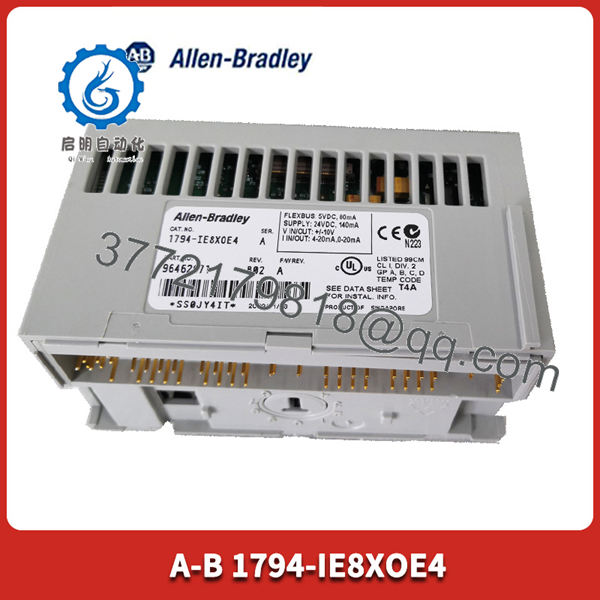
1794-IE8XOE4
Engineering Selection Highlights
- Combined 12-Channel Analog Density: Combines 8 analog inputs and 4 analog outputs in a single module footprint, reducing terminal base hardware requirements and enclosure space.
- Flexibility in Signal Ranges: Configurable for standard industrial voltage (0–10V, ±10V) and current loop (0–20 mA, 4–20 mA) instrument ranges.
- Modular Base Design with RIUP: Mounts on 1794 terminal bases to support Removal and Insertion Under Power, simplifying maintenance and minimizing process downtime during module replacement.
- High-Accuracy 16-Bit Resolution: Delivers precise signal conversion with 0.1% full-scale accuracy at 25°C for process control loops.
- Field-to-System Isolation: Provides 50V continuous basic insulation between field-side circuits and the internal FLEXbus logic backplane.
System Compatibility & Integration Requirements
| Item / Dependency | Verified Compatibility or Requirement | Practical Note |
|---|---|---|
| Network Adapters | FLEX I/O Adapters (1794-AENT, 1794-AENTR, 1794-ACN15, 1794-APB, etc.) | Links the module backplane to EtherNet/IP, ControlNet, or PROFIBUS networks. |
| Terminal Base Units | 1794-TB3, 1794-TB3S, 1794-TB3T, 1794-TB3TS, 1794-TBN | Required for installation; handles field wiring and provides module backplane connection. |
| Controller Software | Studio 5000 Logix Designer, RSLogix 5000, RSLogix 500 | Configured via I/O module profile properties or block transfer write (BTW) / read (BTR) data blocks. |
| External Power Supply | 24V DC Class 2 Power Supply | Provides external power to analog output circuitry and field-side electronics via terminal base connections. |
Dimensions, Mounting & Connection Notes
- Physical Dimensions: Module dimensions are approximately 46 mm (H) x 94 mm (W) x 53 mm (D); total depth increases to approximately 87 mm when mounted on a standard 1794 terminal base.
- Mounting Orientation: Secures onto a 1794 terminal base unit installed on standard 35 mm DIN rail (EN 50022) or mounted directly to a panel backplate.
- Signal Cable Requirements: Use belden-style shielded twisted-pair cabling (e.g., Belden 8761) for all analog input and output signal runs to prevent electrical noise coupling. Cable runs must not exceed 10 m (33 ft).
- Terminal Wiring Gauge: Terminal bases accommodate wire sizes from 0.33 to 2.1 mm² (22 to 14 AWG) solid or stranded copper wire rated for 75°C minimum.
FAQ
What is the channel configuration of the Allen-Bradley 1794-IE8XOE4?
The 1794-IE8XOE4 contains 12 total analog channels organized as 8 single-ended analog inputs and 4 single-ended analog outputs.
Which signal ranges can be configured on the module?
Channels can be configured for voltage signals (0 to 10V DC, ±10V DC) or current loop signals (0 to 20 mA, 4 to 20 mA).
Does the 1794-IE8XOE4 support Removal and Insertion Under Power (RIUP)?
Yes. When mounted on a compatible 1794 terminal base unit, the module can be safely removed and replaced under power without disturbing field wiring or adjacent network communications.
What terminal base units are compatible with the 1794-IE8XOE4?
It is compatible with 3-wire and 4-wire FLEX I/O terminal bases, including the 1794-TB3, 1794-TB3S, 1794-TB3T, 1794-TB3TS, and 1794-TBN base units.
What external power source is required to operate the module?
The module requires an external 24V DC nominal field power supply (operating within a 19.2V to 31.2V DC range) connected through the terminal base power terminals.
Verification & Troubleshooting Notes
- No Module Power / LED Extinguished: Verify that external 24V DC power is present across the power terminals on the terminal base unit. The module requires external DC power in addition to 5V DC power provided by the FLEXbus adapter.
- Incorrect Analog Measurements: Check the configuration word settings in the controller program to ensure channel range selection bits (e.g., 4–20 mA vs. 0–10V) match the physical instrument connected to the terminal.
- Signal Drift or Interference: Confirm that signal wire shielding is grounded at one end only (typically at the cabinet ground bus) and that signal cables are separated from high-voltage AC lines and VFD output motor leads.



