
 WhatsApp: +86 16626708626
 Email:
  Phone: +86 16626708626
Description
Key Technical Specifications
| Parameter | Specification |
|---|---|
| Catalog Number | 1794-OB32P |
| Product Family | Allen-Bradley FLEX I/O |
| Module Type | Digital DC Output |
| Number of Outputs | 32 |
| Output Configuration | Sourcing |
| Output Groups | 2 groups of 16 |
| Nominal Output Voltage | 24 V DC |
| Output Voltage Range | 10–31.2 V DC |
| Maximum Current per Channel | 500 mA |
| Maximum Module Current | 14 A |
| Group Current, Channels 0–15 | 6 A |
| Group Current, Channels 16–31 | 8 A |
| Minimum On-State Current | 1.0 mA/channel |
| Maximum On-State Voltage Drop | 0.5 V DC |
| Surge Current | 2 A for 50 ms, repeatable every 2 s |
| Maximum Off-State Leakage | 0.5 mA |
| Output Delay, Off-to-On | 0.5 ms |
| Output Delay, On-to-Off | 1.0 ms |
| FlexBus Current | 80 mA @ 5 V DC |
| Maximum Power Dissipation | 5.3 W @ 31.2 V DC |
| Isolation Voltage | 50 V continuous, basic insulation |
| Terminal Base | 1794-TB32 / 1794-TB32S |
| Operating Temperature | 0 to 55 °C |
| Protection | Electronic output protection |
Rockwell’s installation documentation specifies 32 sourcing outputs, 500 mA maximum per channel, 14 A maximum module current, and separate 6 A and 8 A limits for the two 16-channel groups. It also specifies 0.5 ms off-to-on and 1.0 ms on-to-off output delays.
Product Introduction
The Allen-Bradley 1794-OB32P is a 32-point protected digital output module for the FLEX I/O system. It provides 24 V DC sourcing outputs arranged as two groups of 16 and is designed to control discrete DC loads such as solenoids, relays, contactors, pilot devices, and indicators. Each output can handle up to 500 mA within the specified group-current limits.
The important engineering distinction is its electronic output protection and high point density. The two output groups have different aggregate current limits, so calculating the load by individual channel alone is not sufficient. Rockwell currently lists the 1794-OB32P as Active Mature and indicates that a replacement is available.
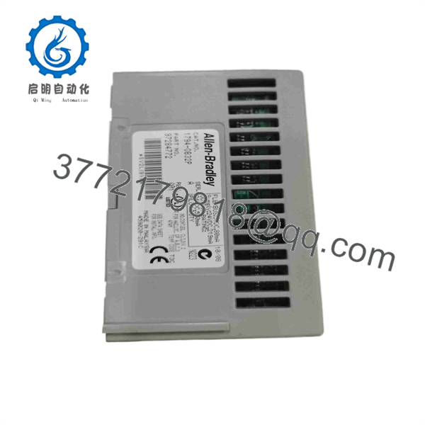
1794-OB32P
Installation & Configuration Guide
Stage 1: Pre-Installation Preparation — 10–15 Minutes
⚠️ Safety First: Place the controlled process in a safe state and follow the site’s electrical isolation/LOTO procedure. The FLEX I/O platform supports Removal and Insertion Under Power (RIUP), but whether RIUP is appropriate depends on the application, system architecture, and site safety procedure. Do not perform an energized replacement simply because the hardware supports RIUP.
Tools Required:
- ESD wrist strap
- Digital multimeter
- Small screwdriver
- Wire labels
- Smartphone/camera
- Laptop with applicable Rockwell software
Data Backup:
- Record the exact 1794-OB32P catalog number and Series.
- Record the adapter/interface module controlling the FLEX I/O station.
- Document the FLEX I/O node address and communication configuration.
- Photograph the terminal base and all 32 output connections.
- Record which field loads correspond to channels 0–15 and 16–31.
- Document the external 24 V DC supply arrangement.
- Record output-group loading before removal.
⚠️ Critical: The two output groups have separate current limits. Rockwell specifies 6 A for channels 0–15 and 8 A for channels 16–31. Do not calculate only against the 14 A module maximum.
Stage 2: Removing the Old Module — 5–10 Minutes
- Place the machine in the approved maintenance state.
- Isolate power if required by the site procedure.
- Verify the field supply voltage with a multimeter.
- Label every output conductor.
- Photograph the terminal arrangement.
- Disconnect the terminal-base wiring if required.
- Release the module from the terminal base.
- Remove the 1794-OB32P without stressing the FLEXBus connection.
- Inspect the terminal base for damaged contacts, loose screws, or overheating.
- Keep the original module until the replacement has passed functional testing.
Stage 3: Installing the New Module — 5–10 Minutes
- Verify the replacement is 1794-OB32P.
- Confirm the module Series and physical condition.
- Verify the terminal base is 1794-TB32 or 1794-TB32S.
- Inspect the module and terminal base for damage.
- Seat the module correctly on the terminal base.
- Confirm the FLEXBus connection is fully engaged.
- Reconnect field wiring according to the original drawings and photographs.
- Verify the 24 V DC supply polarity.
- Confirm that the output groups remain correctly separated.
- Check external protection and load suppression.
Self-Checklist:
- 1794- verified
- Correct terminal base verified
- FLEXBus connection seated
- Channels 0–15 wiring checked
- Channels 16–31 wiring checked
- 24 V DC polarity checked
- Group current calculations checked
- Inductive-load suppression checked
Stage 4: Power-On & Testing — 15–30 Minutes
- Perform a final visual inspection.
- Measure the field supply before energizing the outputs.
- Restore the FLEX I/O station.
- Verify adapter-to-I/O communication.
- Confirm the 1794- is recognized.
- Check module status and diagnostic information.
- Test each output individually where the process permits.
- Verify the commanded output switches the intended field load.
- Confirm outputs turn off correctly.
- Test representative inductive loads under normal operating conditions.
- Check for output-overload or short-circuit indications.
- Verify HMI/SCADA output status.
- Return the process to service after the complete output test.
Common Replacement Pitfalls
❗ 1. Exceeding the Group Current Limit
The module supports 14 A maximum overall, but the two groups have separate limits: 6 A for channels 0–15 and 8 A for channels 16–31. A load calculation that only totals all 32 outputs can miss an overloaded group.
❗ 2. Confusing Sourcing and Sinking Outputs
The 1794- is a sourcing output module. The external wiring must match that architecture. Do not substitute a sinking FLEX I/O output module without reviewing the complete field circuit.
❗ 3. Forgetting the Terminal Base
The 1794- requires a compatible terminal base, such as 1794-TB32 or 1794-TB32S. The output module itself is not a complete field-wiring assembly.
❗ 4. Assuming Electronic Protection Means Unlimited Overload Capacity
The outputs are electronically protected, but that does not make them suitable for arbitrary overloads. Check the load current, inrush, wiring, supply capacity, and group loading.
❗ 5. Ignoring Inductive Load Suppression
Solenoid valves, relays, and contactors generate voltage transients when switched off. Use appropriate suppression at the load where required. This reduces electrical stress on the output circuitry and associated field wiring.
Frequently Asked Questions (FAQ)
1. What is the Allen-Bradley 1794-?
The is a 32-point Allen-Bradley FLEX I/O digital output module providing 24 V DC sourcing outputs. The outputs are electronically protected and divided into two groups of 16.
2. What is the maximum current per 1794- output?
Each output supports up to 500 mA under the specified conditions. However, the group limits must also be respected: 6 A for channels 0–15 and 8 A for channels 16–31.
3. Is the 1794- a sourcing or sinking module?
It is a sourcing 24 V DC output module. If the existing application requires sinking outputs, the 1794- is not a direct functional substitute without changing the field-circuit design.
4. Which terminal base does the 1794- use?
Rockwell specifies 1794-TB32 and 1794-TB32S terminal bases for the 1794-. Verify the terminal-base catalog number before ordering a replacement module.
5. Can the 1794- be hot-swapped?
The FLEX I/O system supports Removal and Insertion Under Power (RIUP), but site procedures and application safety requirements take precedence. For a critical process, an energized module replacement should be performed only when the system design and approved maintenance procedure explicitly allow it.
6. Is the 1794- discontinued?
No. Rockwell Automation currently lists the 1794- as Active Mature and indicates that a replacement is available. The current Rockwell product page also lists an estimated OEM lead time of 5 days and a standard warranty duration of 1 year; actual availability and commercial terms should be confirmed at the time of purchase.
7. What should I verify when buying a surplus 1794-?
Verify the exact catalog number, Series, physical condition, terminal-base compatibility, output-channel operation, and electronic protection status. For a production spare, a proper test should exercise representative outputs and verify both 16-channel groups rather than relying solely on a power-on check.



