
 WhatsApp: +86 16626708626
 Email:
  Phone: +86 16626708626
Description
3. Key Technical Specifications
| Parameter | Value |
|---|---|
| Number of Outputs | 32 (2 groups of 16), sourcing |
| Output Voltage Range | 10–31.2 V DC (24 V DC nominal) |
| On-State Current | 1.0 mA min / 500 mA max per channel |
| Module Current Rating | 14 A max (6 A total channels 0–15; 8 A total channels 16–31) |
| Surge Current | 2 A for 50 ms, repeatable every 2 s |
| On-State Voltage Drop | 0.5 V DC max |
| Off-State Leakage | 0.5 mA max |
| Output Delay (Off to On / On to Off) | 0.5 ms / 1.0 ms max |
| Flexbus Current | 80 mA @ 5 V DC |
| Power Dissipation | 5.3 W max @ 31.2 V DC |
| Thermal Dissipation | 18.1 BTU/hr max @ 31.2 V DC |
| Isolation | 50 V continuous (basic); tested 850 V DC for 60 s (field to system); no channel-to-channel isolation |
| Terminal Base | 1794-TB32 or 1794-TB32S |
| Operating Temperature | 0 to 55 °C (32 to 131 °F) |
| Storage Temperature | –40 to 85 °C (–40 to 185 °F) |
| Status Indicators | 32 yellow LEDs (field-side) |
| Fusing | Electronically protected |
4. Product Introduction
The Allen-Bradley 1794-OB32P is a FLEX I/O 32-point digital DC output module with electronic protection. It provides 32 current-sourcing outputs arranged in two groups of 16. Each group can be powered from a separate external 24 V DC supply. Outputs are protected against short-circuit and overload conditions.
The module mounts on a 1794-TB32 or 1794-TB32S terminal base and draws 80 mA from the Flexbus. It supports Removal and Insertion Under Power (RIUP) when used with a compatible adapter. Maximum continuous current is 14 A per module, with a split of 6 A for the first group and 8 A for the second group. Status LEDs indicate the state of each output.
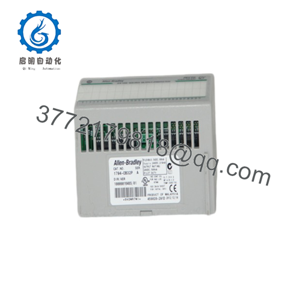
1794-OB32P
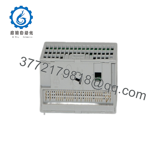
1794-OB32P
5. Installation & Configuration Guide
Stage 1: Pre-Installation Preparation (5–10 min) ⚠️ Safety First: Place the system in a safe state. Lock out/tag out field power and adapter power. Wear an ESD wrist strap. Tools Required: ESD strap, screwdriver, multimeter, smartphone for photos of wiring. Data Backup: Record the existing output mapping, safe-state configuration (if used), and terminal base wiring. Photograph all field connections.
Stage 2: Removing the Old Module (5–8 min)
- Confirm field power and adapter power are removed.
- Note the terminal base type (must be 1794-TB32 or 1794-TB32S).
- Release the module locking tab and pull the module straight off the terminal base.
- Inspect the terminal base contacts for damage or contamination. ⚠️ Keep the old module until the replacement is verified under load.
Stage 3: Installing the New Module (8–12 min)
- Verify the module is marked 1794-OB32P and the terminal base is 1794-TB32 or 1794-TB32S.
- Align the module with the terminal base guides and press firmly until the locking tab engages.
- Connect field power:
- Group 0–15: +V1 to terminals 35/37/39/41, COM1 to 36/38/40/42
- Group 16–31: +V2 to terminals 43/45/47/49, COM2 to 44/46/48/50
- Wire individual outputs to the corresponding terminals on the A-row (0–31).
- Observe polarity and current limits (500 mA per point, group totals as specified). Self-Checklist: [ ] Correct terminal base [ ] Module fully seated [ ] Separate power feeds for each group if required [ ] Total current within limits.
Stage 4: Power-On & Testing (10–15 min)
- Apply Flexbus power, then field power.
- Observe the 32 yellow status LEDs.
- Force or program individual outputs and verify field devices respond.
- Confirm no electronic protection trips under normal load.
- Check module status in the controller (fault bits, connection status). ⚠️ Troubleshooting Note: Outputs that remain off with the LED on usually indicate open field wiring or a tripped electronic protection. Cycle power after clearing a short. Exceeding group current limits will cause protection to activate.
6. Frequently Asked Questions (FAQ)
Q: Can the 1794-OB32P be hot-swapped? Yes for the module itself when used with a supporting adapter (Removal and Insertion Under Power). Always remove field power before changing wiring on the terminal base.
Q: Is the 1794-OB32P still in production? No. Many FLEX I/O digital modules, including the 1794-OB32P, are discontinued or limited. Remaining stock is new surplus or refurbished. For new designs, consider 1734 POINT I/O or 1756 ControlLogix equivalents.
Q: What terminal base is required? Only the 1794-TB32 or 1794-TB32S. Other FLEX terminal bases are not compatible with the 32-point pinout.
Q: How is the current limited? Each channel is electronically protected to 500 mA. The module total is limited to 14 A (6 A for channels 0–15 and 8 A for channels 16–31). Separate external power supplies are recommended for each group when loads approach these limits.
Q: Why is the price lower than historical OEM list price? These are genuine surplus units from excess inventory. They are original Allen-Bradley modules that have never been installed in a running system, but they are no longer available through standard Rockwell channels. Functional testing and warranty are provided.
Q: Are the outputs isolated from each other? No. Channels within each group of 16 share a common return. Isolation exists only between the field side and the system (Flexbus).
Q: What is the safe-state behavior? The module supports a configurable safe-state (SSData) that defines the output values applied if communication is lost. Configure this in the controller project if required for your application.



