
 WhatsApp: +86 16626708626
 Email:
  Phone: +86 16626708626
Description
Key Technical Specifications
| Parameter | Value |
| Catalog Number | 1794-OE12 |
| Number of Outputs | 12 single-ended, non-isolated channels |
| Output Ranges | 0–20 mA, 4–20 mA (Current) / ±10 V, 0–10 V, ±5 V, 0–5 V (Voltage) |
| Resolution | 16-bit (0.305 µA/cnt current, 320 µV/cnt voltage) |
| Conversion Rate | 8.0 ms all channels |
| Accuracy | Current: 0.1% Full Scale at 25°C / Voltage: 0.1% Full Scale at 25°C |
| External DC Source Voltage | 24 VDC nominal (10.5–31.2 VDC including ripple) |
| External DC Current Draw | 200 mA at 24 VDC |
| Flexbus Current Load | 80 mA at 5 VDC |
| Terminal Base Compatibility | 1794-TB32, 1794-TB32S (32-wire terminal bases) |
| Operating Temperature | 0 to 55°C (32 to 131°F) |
Product Introduction & Supply Chain Strategy
The Allen-Bradley 1794-OE12 is a high-density, 16-bit analog output module designed for the modular Flex I/O system. Providing 12 independently configurable voltage or current outputs, it drives variable frequency drives (VFDs), control valves, positioning actuators, and analog meters across distributed process applications.
As Rockwell Automation moves legacy Flex I/O platforms toward End-of-Life (EOL) status, securing uncompromised New Surplus units is vital for maintaining process accuracy. Sourcing factory-sealed New Surplus eliminates the hidden dangers of internal component drift, degraded digital-to-analog converter (DAC) chips, and thermal aging common in refurbished modules. Keeping on-site buffer stock guards against sudden process control failures, protecting overall plant Total Cost of Ownership (TCO).
Installation & Configuration Guide
Stage 1: Pre-Installation (Prep & Safety)
- Lock-Out/Tag-Out (LOTO): Isolate and lock out all 24 VDC power supplies and field current loops connected to the 1794 terminal base.
- Terminal Base Verification: Ensure the module is mated with a 32-wire terminal base unit (1794-TB32 or 1794-TB32S) to provide adequate terminal points for all 12 channels.
- ESD Precautions: Wear a grounded anti-static wrist strap before touching the module to prevent static discharge to the internal flexbus circuits.
Stage 2: Removal
- Turn the keyswitch on the terminal base counterclockwise to match the module keying position (Position 4 for analog modules).
- Press the upper and lower module latch mechanisms on the terminal base unit.
- Pull the failed 1794-OE12 card straight out off the terminal base keyswitch post to clear backplane pins.
Stage 3: Installation (Clone & Seat)
- Verify that the terminal base keyswitch is aligned to Position 4.
- Align the rear connector of the new 1794-OE12 with the terminal base header and press firmly until the side locking latches snap into place.
- Connect field signal wiring (shielded twisted-pair cable) to designated channel terminals, terminating shields cleanly at the chassis ground bar.
Stage 4: Power-On & Testing
- Apply 24 VDC external loop power and flexbus logic power; observe the front-panel Power LED.
- Verify the Power LED turns solid green, indicating valid 24 VDC auxiliary field supply voltage.
- Force output values (e.g., 4 mA, 12 mA, 20 mA) via RSLogix 5000 / Studio 5000 software and measure terminal signal levels using a calibrated digital multimeter.
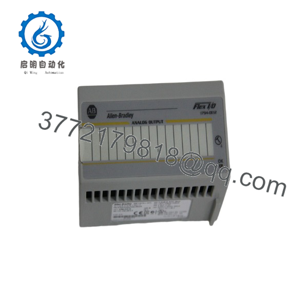
1794-OE12
Firmware/Software Versions & Upgrade Notes
- Software Configuration: Configured using Studio 5000 Logix Designer or RSLogix 5000 I/O tree configuration windows.
- I/O Profile Integration: Ensure the 1794-OE12 Electronic Data Sheet (EDS) or Add-On Profile (AOP) matches the revision registered in your Logix controller project.
- Power Budgeting: Calculate total 24 VDC auxiliary current demand. Each active 4–20 mA channel draws field power; ensure external 24 VDC power supply sizing includes a 20% safety margin to prevent voltage droops under full-scale output conditions.
Frequently Asked Questions (FAQ)
Is this 1794-OE12 unit guaranteed to be New Surplus and not refurbished?
Yes. This module is 100% Brand New Surplus in original OEM factory packaging. It has never been deployed in an active control panel, subjected to industrial thermal cycling, or repaired. Internal DAC circuitry and flexbus pins remain in pristine factory condition.
Why is buying New Surplus so critical for high-density analog modules like the 1794-?
Analog modules rely on precision voltage references and calibrated resistor networks. Refurbished modules frequently suffer from component aging, signal drift, and thermal damage caused by continuous high-current field loop operation. Buying New Surplus guarantees factory-level 0.1% accuracy and full 16-bit signal linearity.
Can I mix current and voltage outputs on the same 1794- module?
Yes. Each of the 12 output channels can be individually configured via software for current (0–20 mA, 4–20 mA) or voltage (±10 V, 0–10 V, ±5 V, 0–5 V) operation based on your field device requirements.
Can I hot-swap the 1794- module while system power is active?
Yes. The Flex I/O system supports Removal and Insertion Under Power (RIUP) on individual terminal base modules. However, ensure field wiring loops are isolated or put in manual override mode to prevent unexpected actuator or valve movements during replacement.
What warranty protection comes with this New Surplus module?
We support this 1794- New Surplus analog output card with a comprehensive 1-year replacement warranty. Every unit passes visual inspection, terminal pin checks, and anti-static moisture-barrier packaging prior to dispatch.



