
 WhatsApp: +86 16626708626
 Email:
  Phone: +86 16626708626
Description
3. Key Technical Specifications
| Parameter | Value |
|---|---|
| Catalog Number | 1794-TB3 |
| Termination Type | Screw clamp |
| I/O Terminals | 16 |
| Common Terminals | 18 |
| +V / Supply Terminals | 18 |
| Current Capacity, Max | 10 A |
| Voltage Rating (V/COM Terminals) | 125 V AC/DC, 50/60 Hz, 10 A |
| FlexBus Current | 5 V DC, 640 mA |
| I/O Terminal Current, Max | 2 A |
| Wire Size | 0.34…3.3 mm² (22…12 AWG) solid or stranded copper |
| Terminal Screw Torque | 0.56…0.79 N·m (5…7 lb·in) |
| Isolation Voltage | 125 V continuous, basic insulation (field to FlexBus) |
| Dimensions (with module installed) | 94 × 94 × 69 mm (3.7 × 3.7 × 2.7 in.) |
| Compatible Modules | 1794-IB8, IB16, IB16XT, OB8, OB16, OA8, OA16, IV16, and many other digital/analog modules |
| Mounting | DIN rail |
| Enclosure Type | None (open-style) |
| Operating Temperature | 0…55 °C (determined by installed module) |
4. Product Introduction
The Allen-Bradley 1794-TB3 is a 3-wire screw-clamp terminal base for the FLEX I/O platform. It provides 16 I/O terminals plus dedicated common and +V terminals, making it suitable for 3-wire sensors and actuators without external distribution blocks.
The base mounts on DIN rail, carries the FlexBus communication and power between modules, and supports Removal and Insertion Under Power (RIUP). It is the standard terminal base for many 8- and 16-point digital input and output modules as well as selected analog modules. Field wiring lands directly on the base so modules can be replaced without disturbing the wiring.
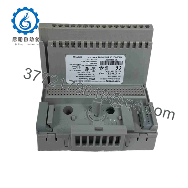
1794-TB3
5. Troubleshooting Quick Reference
| Symptom | Possible Cause | Relevance to this Part | Quick Check Method | Recommendation |
|---|---|---|---|---|
| Module will not seat or power | Wrong keyswitch position or damaged latch | ✅ High | Verify keyswitch matches the module and inspect latch | Set correct key position; replace base if damaged |
| No field power to devices | Loose or missing +V / common connections | ✅ High | Measure voltage at +V and common terminals | Check and retighten power wiring |
| Intermittent I/O signals | Loose terminal screws or poor wire contact | ✅ High | Torque all terminals to 0.56…0.79 N·m | Re-terminate and torque properly |
| FlexBus communication loss | Bent or dirty FlexBus connector | ✅ Medium | Inspect FlexBus pins between bases | Clean or replace base if pins are damaged |
| Overheating at terminals | Exceeded 10 A total current | ✅ Medium | Calculate total current through the base | Split power feeds or reduce load |
| Module reports terminal base fault | Incompatible base or wiring error | ✅ Low | Confirm module is listed for 1794-TB3 | Use correct base for the specific module |
If problems persist after these checks, photograph the terminal wiring, keyswitch position, and module face, then contact technical support.
6. Frequently Asked Questions (FAQ)
Q: What is the difference between the 1794-TB3 and 1794-TB3S?
A: The 1794-TB3 uses screw-clamp terminals. The 1794-TB3S uses spring-clamp terminals for faster wiring. Electrical ratings and terminal assignments are the same.
Q: Can I use the 1794-TB3 with 32-point modules?
A: No. 32-point modules require the 1794-TB32 or 1794-TB32S terminal base.
Q: Does it support Removal and Insertion Under Power (RIUP)?
A: Yes. When used with compatible FLEX I/O modules and adapters, modules can be removed and inserted under power.
Q: What is the maximum current through the terminal base?
A: 10 A total through the V/COM terminals. Individual I/O terminals are limited to 2 A.
Q: What wire size is accepted?
A: 0.34…3.3 mm² (22…12 AWG) solid or stranded copper wire rated 105 °C or higher.
Q: Is the 1794-TB3 still in production?
A: Yes. It remains a standard FLEX I/O terminal base. New original and new-surplus units are available.
Q: Can I daisy-chain power between multiple bases?
A: Yes. The +V and common terminals support daisy-chaining, provided the total current stays within the 10 A limit.



