
 WhatsApp: +86 16626708626
 Email:
  Phone: +86 16626708626
Description
Key Technical Specifications
| Parameter | Value |
|---|---|
| Model Number | F-4030-Q-H04AA |
| Legacy Part Number | 193490 |
| Brand | Allen-Bradley / Rockwell Automation |
| Original Motor Manufacturer | Electro-Craft / Reliance Electric legacy F-Series |
| Product Series | F-Series brushless servo motors |
| Product Type | Brushless permanent-magnet AC servo motor |
| Motor Inertia Class | Medium inertia |
| Rated Input | 240 V AC, three phase |
| Rated Current | 4.6 A |
| Continuous Power | 1.9 HP / approximately 1.4 kW |
| Maximum Speed | 4,000 RPM |
| Continuous Torque | 31 lb-in / approximately 3.5 N·m |
| Feedback Device | Optical incremental encoder |
| Encoder Resolution | 2,000 lines per revolution |
| Holding Brake | 24 V DC electromagnetic holding brake |
| Brake Function | Holds stationary load; not intended for dynamic stopping |
| Motor Frame | 4030 medium-inertia frame |
| Shaft Type | Standard keyed output shaft; verify actual nameplate and shaft dimensions |
| Mounting | Standard F-Series flange; verify pilot, bolt pattern, and shaft geometry |
| Motor Enclosure | Commonly listed as IP65 when correctly installed |
| Recommended Ambient Temperature | 0 to +40 °C |
| Storage Temperature | −30 to +70 °C |
| Approximate Weight | 23.9 lb / 10.9 kg |
| Lifecycle Status | Discontinued / legacy servo motor |
The F-4030-Q-H04AA is a legacy F-Series brushless servo motor, not a current Kinetix motor model. The “Q” suffix identifies the 24 V DC holding brake, and the “H04” code identifies a 2,000-line optical encoder. Confirm the full motor catalog number, serial-number label, brake voltage, encoder connector, cable part number, shaft configuration, and drive feedback compatibility before ordering.
Product Introduction
The Allen-Bradley F-4030-Q-H04AA is a medium-inertia, brushless AC servo motor for legacy Rockwell Automation, Reliance Electric, and Electro-Craft motion-control systems. It provides approximately 1.9 HP, 31 lb-in continuous torque, and up to 4,000 RPM from a 240 V AC three-phase servo drive, with an integrated 24 V DC holding brake.
This model is used on packaging equipment, CNC feed axes, printing machinery, robotics, and material-handling systems where the installed drive requires F-Series motor feedback. The 2,000-line encoder and brake configuration must match the existing drive, cable, and machine mechanics. A physically similar motor is not automatically an electrically compatible replacement.
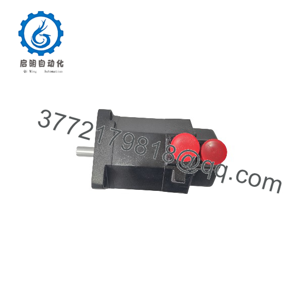
F-4030-Q-H04AA
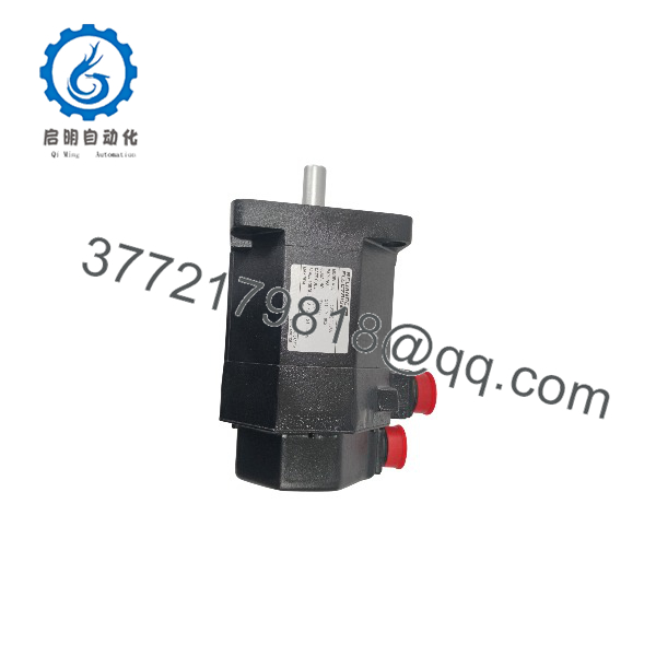
F-4030-Q-H04AA
Troubleshooting Quick Reference
| Symptom | Possible Cause | Relevance to This Part | Quick Check Method | Recommendation |
|---|---|---|---|---|
| Servo drive reports encoder loss or feedback fault | Damaged encoder cable, loose connector, encoder power loss, incorrect feedback type, failed encoder | ❌ Usually cable or drive-related | Power down safely; inspect encoder connector pins and cable shield; test with a known-good compatible cable; review drive feedback diagnostics | Replace cable or correct drive setup before condemning the motor encoder |
| Motor will not enable but drive powers normally | E-stop chain open, drive inhibit active, brake not releasing, encoder fault, incorrect motor parameters | ❌ Usually drive, brake, or control wiring | Review drive fault code; confirm 24 V DC reaches brake coil during enable; verify motor parameters and feedback configuration | Clear the actual drive fault. Do not replace the motor based only on a no-enable condition |
| Motor hums but shaft will not turn | Holding brake remains engaged, mechanical load jammed, phase connection fault, drive current limit active | ✅ Medium | With machine secured, confirm brake release voltage at motor connector; disconnect mechanical load if approved; check drive current and phase output | If 24 V DC is present and brake does not release, inspect brake coil or motor. Do not force the shaft |
| Motor shaft turns but load does not move | Loose coupling, stripped key, failed gearbox, broken belt, slipping pulley, mechanical disconnect | ❌ Usually mechanical | Lock out power and inspect coupling, keyway, belts, gearbox input, and load-side shaft marks | Repair the mechanical transmission. The servo motor may be healthy |
| Motor runs rough or vibrates excessively | Misaligned coupling, damaged bearings, tuning issue, encoder noise, loose mounting, load resonance | ✅ Medium | Check mounting bolts and coupling alignment; run uncoupled only if safe; compare vibration with a known-good axis; inspect drive tuning | Correct alignment and tuning first. Replace or repair motor if vibration remains with no load |
| Drive trips on overcurrent during acceleration | Mechanical binding, excessive inertia, wrong motor parameters, phase short, brake dragging, damaged bearings | ✅ Medium | Check commanded acceleration, observe torque/current trend, verify brake release, and inspect machine for binding | Reduce acceleration only if process design permits; repair mechanical fault before replacing motor |
| Motor overheats during normal operation | Overloaded axis, poor cooling, high ambient temperature, incorrect tuning, phase imbalance, bearing wear | ✅ Medium | Measure motor surface temperature, drive current, duty cycle, cabinet ambient, and axis friction | Compare running current to the motor/drive design. Correct load or tuning issues before motor replacement |
| Motor brake will not hold vertical axis | Brake coil open, brake friction worn, 24 V DC wired incorrectly, load exceeds brake rating, mechanical backlash | ✅ High | Secure the axis with external support; remove brake power and observe holding; measure coil resistance and verify no 24 V DC remains on the brake | Do not rely on a failed brake for personnel or load protection. Repair or replace motor/brake and inspect counterbalance system |
| Motor drops load when servo is disabled | Brake not wired, brake supply fails, brake release signal remains energized, brake worn, vertical axis improperly designed | ✅ Critical | Secure the load mechanically; measure brake voltage before and after disable; verify brake-control relay logic | Stop operation until corrected. A holding brake is not a substitute for mechanical load restraint or safe brake control |
| Motor fails insulation test or ground fault occurs | Damaged motor cable, coolant/oil ingress, winding insulation damage, contaminated connector | ✅ High | Disconnect motor from drive; inspect cable and connectors; perform insulation testing only at the manufacturer-approved voltage with encoder and brake circuits isolated | Do not megger through encoder or brake electronics. Repair cable or send the motor for qualified evaluation |
| Replacement motor produces encoder fault immediately | Wrong encoder code, pinout mismatch, incompatible cable, drive expects different feedback scaling | ✅ High | Compare old and new nameplates, encoder code, connector type, cable assembly, and drive configuration character by character | Use an exact F-4030-Q-H04AA or verified form-fit-function replacement with confirmed feedback compatibility |
| Replacement motor does not mount correctly | Wrong flange, shaft diameter, shaft length, key size, pilot diameter, or brake length | ❌ Mechanical fit issue | Measure old motor flange, pilot, shaft, key, and overall length before removal | Confirm mechanical dimensions before ordering. Do not machine or modify the shaft without engineering approval |
| Drive faults after a motor cable change | Phase leads swapped, shield termination wrong, encoder plug misaligned, brake wires reversed, cable damaged | ❌ Installation-related | Compare every conductor and shield connection against the cable drawing; inspect connector keying and pin engagement | Do not wire from memory. Restore the approved cable pinout and verify before energizing |
❗ Encoder warning: The H04 configuration uses a 2,000-line optical incremental encoder. Do not substitute an F-Series motor with a different encoder code simply because the flange and shaft match. A mismatched feedback device can create position loss, runaway alarms, incorrect commutation, or an immediate drive fault.
❗ Brake warning: The Q suffix identifies a 24 V DC electromagnetic holding brake. It is intended to hold a stopped axis, especially a vertical load. It is not a dynamic stopping brake. Do not repeatedly use it to stop a moving axis; that overheats and wears the brake friction surfaces.
❗ Stored-energy warning: Secure vertical axes, suspended loads, and gravity-driven mechanisms before removing brake power or uncoupling the motor. I have seen a technician disable the servo to test a brake and discover the counterbalance cylinder had no pressure. The axis dropped before anyone could react.
❗ Insulation-test warning: Never apply a megger across the encoder circuit, brake leads, or a connected servo drive. Isolate the motor’s three power phases from the drive, follow the motor manufacturer’s approved test voltage, and keep the low-voltage feedback and brake circuits separate.
If diagnostics remain unclear, contact technical support with full nameplate photos, drive model and fault code, motor and cable part numbers, encoder connector photos, brake-voltage measurement, motor current trend, mechanical-axis description, and insulation-test record. Keep these checks in mind and you will save yourself most of the usual rework time.
Frequently Asked Questions
What is the Allen-Bradley F-4030-Q-H04AA?
The F-4030-Q-H04AA is a legacy brushless AC permanent-magnet servo motor from the F-Series family supported across older Allen-Bradley, Reliance Electric, and Electro-Craft motion systems. It is a medium-inertia 240 V AC motor with approximately 1.9 HP output, 31 lb-in continuous torque, 4,000 RPM maximum speed, a 2,000-line optical encoder, and a 24 V DC holding brake.
What does the “Q-” suffix mean?
The available F-Series references identify the Q code as a standard 24 V DC electromagnetic holding brake and H04 as a 2,000-line optical encoder. The remaining mechanical suffix must still be verified against the actual nameplate and dimensional drawing because flange, shaft, connector, and mounting details matter for a direct replacement.
Can I replace this motor with a current Kinetix servo motor?
Not as a direct plug-in replacement. A modern Kinetix motor may require a different drive, feedback protocol, cable set, flange adapter, motor parameters, brake wiring, and tuning procedure. Even if the power rating is close, the encoder and commutation requirements can make it incompatible with the existing legacy drive.
For minimal downtime, source an exact F-4030-Q- or a documented form-fit-function replacement that explicitly confirms electrical feedback, brake, shaft, flange, and drive compatibility. Elwood lists this model as a legacy F-Series motor it supports for replacement or service.
Can I use the motor brake to stop the machine?
No. The 24 V DC brake is a holding brake. Use the servo drive’s controlled deceleration, torque-off sequence, safety function, or engineered mechanical braking system to stop the axis. Apply the brake only once the motor has slowed or stopped, according to the machine control sequence.
Repeated dynamic stopping with the holding brake can overheat it, wear the friction surfaces, and eventually allow a vertical axis to creep or fall.
Why does the drive report an encoder fault after I install a replacement motor?
The usual causes are a mismatched encoder code, incompatible cable, wrong connector pinout, damaged feedback cable, missing encoder supply, incorrect drive configuration, or connector pins that are bent or not fully engaged. Confirm that the replacement is specifically the H04 2,000-line encoder version and that the existing drive supports that feedback.
Do not change encoder scaling randomly in the drive to clear a fault. Start with model, cable, pinout, supply voltage, and drive documentation.
Can I test the servo motor with a standard insulation tester?
Only the isolated three-phase motor power winding may be tested, and only at the manufacturer-approved voltage. Disconnect the motor fully from the drive, isolate encoder and brake circuits, and use a qualified procedure. Do not megger through the drive, encoder, or 24 V DC brake; the test voltage can destroy low-voltage electronics.
If the motor has coolant, oil, washdown exposure, or cable damage, inspect connectors and cable insulation first. The cable is often the problem, not the winding.
Is the F-4030-Q- obsolete?
Yes. It is identified in supplier references as discontinued by the manufacturer and is part of a legacy F-Series servo family. New Original stock, New Surplus, professionally rebuilt motors, and third-party form-fit-function replacements are the practical sourcing routes. For critical production equipment, keep the motor’s nameplate data, compatible cable information, drive parameters, and a verified spare strategy.
How should a New Surplus F-4030-Q- be tested before shipment?
Start with inspection and traceability: confirm the entire F-4030-Q- catalog number, 193490 legacy number where present, serial number, shaft/key condition, flange, connector condition, brake marking, encoder code, housing, and absence of corrosion, impact damage, fluid ingress, rework marks, or damaged bearings.
For live testing, mount the motor securely on a controlled servo test stand with a verified compatible drive, matched feedback cable, correct 240 V AC three-phase input, and safeguarded rotating components. Verify encoder feedback, direction, low-speed stability, speed operation toward the rated 4,000 RPM limit, no-load current, vibration, temperature rise, and fault-free operation. Test the 24 V DC brake for release and holding function only after mechanically securing the shaft or load.
Perform winding resistance and phase-balance checks. Conduct insulation-resistance testing on isolated motor power windings only, with encoder and brake circuits disconnected. Run the motor for more than 24 hours at representative duty while monitoring current, vibration, bearing noise, feedback stability, brake operation, and thermal rise. Document the test drive model, feedback cable, brake voltage, measured current, speed, vibration condition, insulation result, and final QC sign-off. Package the motor with shaft protection, connector caps, ESD-safe feedback protection, foam support, and a heavy-duty corrugated box. Test photos and video should be available upon request. Available references identify this motor as a 240 V AC, 4.6 A, 1.9 HP, 4,000 RPM F-Series servo with a 24 V DC brake and 2,000-line optical encoder.



