
 WhatsApp: +86 16626708626
 Email:
  Phone: +86 16626708626
Description
3. Key Technical Specifications
| Parameter | Value |
|---|---|
| Manufacturer | Valmet Automation |
| Model Number | 542936-2A |
| Alternate Revision | 542936-2B |
| Platform | PMB 1S |
| Module Type | PLC Connection Module |
| Board Identification | MT119 |
| Installation Method | Rack Mounted |
| Application | PLC/SCU Communication Interface |
| Country of Manufacture | Finland |
| Approximate Weight | 180-190 g |
| System Generation | Legacy Valmet DCS/PLC Platform |
| Availability Status | Obsolete / Surplus Market Only |
4. Product Introduction
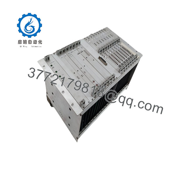
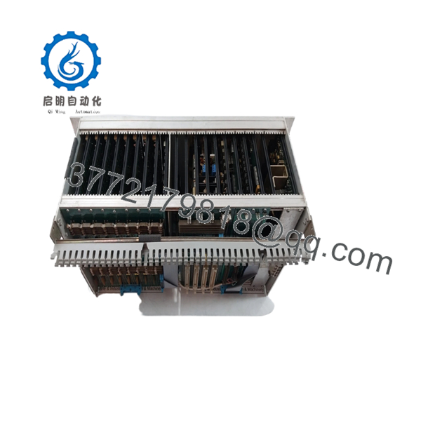
The VALMET 542936-2A is a PLC Connection Module used within Valmet PMB 1S control system architectures. It functions as an interface board between controller hardware and associated rack communication assemblies in legacy Valmet automation installations.
Engineers typically source this module when maintaining existing PMB 1S systems where a complete platform migration is not yet justified. The primary advantage is maintaining hardware compatibility with installed Valmet racks while avoiding extended production downtime associated with major control system upgrades.

- 542936-2A
- 542936-2A
5. Installation & Configuration Guide
Stage 1: Pre-Installation Preparation (10 Minutes)
⚠️ Safety First
- Notify operations and schedule downtime.
- Place the process in a safe state.
- Apply Lock-Out/Tag-Out (LOTO).
- Remove control power.
- Wait at least 5 minutes for capacitor discharge.
Tools Required
- Grounded ESD wrist strap
- PH1 screwdriver
- Fluke 115 multimeter (or equivalent)
- Wire markers
- Smartphone for documentation
- Flashlight
Data Backup
- Export controller configuration.
- Record all network settings.
- Photograph:
- Terminal wiring
- Module location
- DIP switch positions
- Jumper settings
- Save the controller backup to two separate locations.
Stage 2: Removing the Old Module (5 Minutes)
- Remove front covers if installed.
- Label all field connections.
- Disconnect wiring carefully.
- Release rack retaining clips.
- Pull the module straight out.
⚠️ Important
Do not rock the module side-to-side excessively. Legacy Valmet backplane connectors can become brittle with age.
Inspection
Check:
- Bent connector pins
- Corrosion
- Dust accumulation
- Oxidation on edge connectors
⚠️ Note
Keep the original module available until the replacement has operated successfully for at least one production shift.
Stage 3: Installing the New Module (10 Minutes)
Step 1 – ESD Protection
- Connect wrist strap to grounded point.
- Handle the board by its edges only.
Step 2 – Configuration Clone (CRUCIAL)
- Compare part number:
- 542936-2A
- Revision level
- Replicate:
- DIP switches
- Jumper settings
- Node addresses
- Bus termination settings
❗ This is the most common rookie mistake, but it happens constantly. Take a picture before you pull it. I can’t stress this enough.
Step 3 – Install Module
- Align guide rails.
- Insert evenly.
- Press firmly until fully seated.
- Verify locking tabs engage.
Step 4 – Reconnect Wiring
- Reconnect cables exactly as documented.
- Tighten terminals using proper torque.
- Verify shield grounding continuity.
Self-Checklist
- Model numbers match
- DIP switches duplicated
- Wiring secured
- Module fully seated
- Locking tabs engaged
Stage 4: Power-On & Testing (15 Minutes)
Pre-Power Check
Using a multimeter:
- Verify no short circuit exists on the 24 V supply.
- Confirm ground continuity.
Power-Up Sequence
- Energize the rack only.
- Observe LED indications.
- Verify normal boot sequence.
- Connect engineering workstation.
- Confirm module detection.
- Verify firmware revision.
- Restore configuration if required.
- Perform I/O simulation.
Functional Verification
- Communication handshake
- Controller diagnostics
- Alarm status
- I/O operation
- Process variable updates
⚠️ Troubleshooting Note
- Solid Red ERR LED → firmware mismatch or hardware fault.
- No communication → verify addressing, cabling, and switch settings.
- Intermittent faults → inspect backplane connector condition.
6. Frequently Asked Questions (FAQ)
Q1. Can I hot-swap the VALMET 542936-2A?
No.
Most PMB 1S installations were not designed for live replacement of communication interface boards. Removing the module under power can corrupt rack communications or damage the backplane. Shut down control power before replacement.
Q2. Is the VALMET 542936-2A obsolete?
Yes.
The PMB 1S platform belongs to an older generation of Valmet automation hardware. Most units currently available come from surplus inventories, decommissioned plants, or specialized automation suppliers. Stock levels are typically limited.
Q3. Is this module genuinely new?
That depends on the supplier.
For legacy Valmet hardware, inventory generally falls into three categories:
- Factory Sealed
- New Surplus (never installed)
- Refurbished (tested)
Always request photographs of serial labels and inspection reports before purchasing.
Q4. Will I lose my control logic if I remove this module?
Normally no.
The 542936-2A functions as a communication/interface module rather than the primary logic memory device. However, always create a complete controller backup before maintenance. Never assume a 30-year-old control system behaves exactly like the documentation suggests.
Q5. What should I verify before ordering a replacement?
Verify:
- Part number (542936-2A)
- Hardware revision
- PMB platform version
- Connector style
- Firmware compatibility
I’ve seen projects where a technician installed a newer hardware revision and spent two days chasing communication timeouts. The root cause turned out to be a revision mismatch.
Q6. Why are some market prices dramatically different?
Condition and traceability.
A tested surplus module with documented load testing, firmware verification, and warranty coverage commands a higher price than an untested warehouse pull. When a paper machine or power plant loses production, the difference between a 300 module and a 3,000 module becomes insignificant compared to downtime costs.
Q7. What quality-control process should be performed before shipment?
A proper inspection process should include:
Inbound Inspection & Traceability
- OEM label verification
- Serial number recording
- Visual inspection for corrosion, scratches, rework marks, and UV discoloration
- Accessory audit
Functional Testing
- Installation in a PMB-compatible test rack
- Power-on verification
- Communication testing
- I/O simulation
- Minimum 24-hour operational run
Electrical Testing
- Insulation resistance test using 500 V Megger (>10 MΩ)
- Ground continuity verification
- Hipot testing where applicable
Firmware Verification
- Firmware identification
- Hardware revision recording
- DIP switch documentation
Final QC
- Inspector sign-off
- ESD packaging
- Heavy-duty protective boxing
- QC label with test date
Request test photos and videos whenever possible. Verified functionality under load testing is far more valuable than a simple statement that the unit is “working.”
Common Replacement Pitfalls
❗ Firmware Revision Mismatch
Document the installed revision before removal. Small firmware differences can cause communication failures that are difficult to diagnose.
❗ DIP Switch Errors
Take photos before touching anything. This single step prevents a large percentage of startup issues.
❗ Terminal Block Differences
Even similar Valmet revisions can have connector changes. Verify wiring diagrams instead of relying on memory.
❗ Power Budget Miscalculations
Check total rack consumption and maintain at least a 20% power supply margin.
❗ ESD Damage
Use a grounded wrist strap and ESD mat. One static discharge can destroy a legacy module that may take months to replace.
Keep these checks in mind and you’ll save yourself 90% of typical rework time.


