
 WhatsApp: +86 16626708626
 Email:
  Phone: +86 16626708626
Description
Key Technical Specifications
| Parameter | Specification Value |
| Manufacturer | Alstom / AEG |
| Model / Part Number | 029.040 967 (Alternate Part No: 029040967) |
| Material Code | MAT. CODE: 10000016787 / 0000016787 |
| Form Factor / Module Type | 8TE Width Insert Card (Standard Eurocard Rack Assembly) |
| Primary Rails Output 1 | +15 V DC @ 0.4 A |
| Primary Rails Output 2 | −15 V DC @ 0.4 A |
| Auxiliary High Voltage Output | +60 V DC @ 0.15 A (Configured for specialized signaling/biasing loops) |
| Backplane Connector | High-density gold-plated DIN multi-pin connector |
| Cooling Profile | Natural convection via rack ventilation slots |
| Construction Layout | Multi-layer rigid industrial PCB with integrated test points |
| Unit Net Weight | 280 g |
| Operating Temperature | −10 to +60 °C |
Product Introduction & Supply Chain Strategy
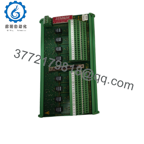
The Alstom 029.040 967 is an industrial-grade, rack-mounted PCB insert card current supply module engineered for critical control and automation systems. It functions as an internal decentralized power node, accepting raw bus input voltage and converting it into highly stable, isolated output rails of ±15 V DC and +60 V DC. These precise voltages are mandatory for driving internal operational amplifiers, analog processing circuits, communication interfaces, and specialized auxiliary signaling loops inside legacy Alstom and AEG switchgear setups or turbine controllers.
From a supply chain perspective, the 029.040 967 falls strictly under the high-criticality class of your ABC inventory matrix. Because this single card provides power directly to multiple adjacent processing cards in the subrack, its failure immediately shuts down the entire multi-card automation bundle. Rather than converting the entire subrack to modern architecture—which incurs immense re-engineering costs, programming delays, and extended downtime—retaining 1–2 New Surplus units as an on-site buffer stock ensures a zero-hour recovery option. This inventory technique dramatically lowers the Total Cost of Ownership (TCO) by avoiding the thermal stress risks and rapid component breakdown associated with refurbished or second-hand electronics.

- 029.040 967
Installation & Configuration Guide
Stage 1: Pre-Installation (Prep & Safety)
- Turn off all main AC and auxiliary DC breaker lines supplying power to the destination card rack or cabinet housing.
- Fasten a grounded, static-dissipative wrist strap to your arm before unboxing the new Alstom 029.040 967 card to prevent any latent ESD breakdown on the exposed capacitors and solid-state surface devices.
- Inspect the rear multi-pin DIN plug of the replacement board to verify all contact tracks are perfectly straight, unbent, and free from oxidation or dirt.
- Verify the card matches the mechanical slot constraints (8TE width) and correct subrack rail guide alignments.
Stage 2: Removal
- Unfasten any front panel retaining screws locking the legacy card into the subrack frame using an insulated precision tool.
- Grasp the integrated plastic ejector tabs on the front faceplate of the board and pull them outward simultaneously to break the backplane mechanical connection friction.
- Smoothly slide the board forward out of the subrack channel tracks, keeping the card level to avoid touching or snagging neighboring cards.
- Clean the empty rack track channel using a vacuum or compressed air to extract accumulated conductive dust.
Stage 3: Installation (Clone & Seat)
- Slide the new Alstom 029.040 967 card into the open track guide rails of the subrack slot, ensuring perfect alignment with the rear backplane mating socket.
- Push the card in firmly until the front plate sits flat against the rack profile and the ejector clips lock down securely.
- Hand-tighten the integrated front panel retention screws to lock the card against structural vibrations caused by surrounding high-voltage breakers.
- Double-check that all neighboring boards remain completely seated and have not been displaced during the intervention.
Stage 4: Power-On & Testing
- Re-energize the primary control power lines to the subrack.
- Confirm the green status LEDs on the front faceplate illuminate steadily, indicating normal operation across the ±15 V DC and +60 V DC lines.
- Using a digital multimeter at the designated front test points (if present), confirm that voltages stay within their respective ±2% tolerance specifications under active load.
- Monitor the processing rack loop behavior for 15 minutes to guarantee protocol handshakes and analog sensor signaling remain completely stable.
Firmware/Software Versions & Upgrade Notes
The Alstom 029.040 967 is a purely hardware-driven, analog linear/switching current supply unit. It does not incorporate microcontrollers, flash memories, or programmable digital code blocks, rendering field firmware updates completely unnecessary.
- Hardware Component Verification: When ordering or performing swaps, ensure the sub-model suffix match (e.g.,
/18vs/19) aligns with your facility’s documentation ledger. Suffix variations often designate subtle modifications to current limiting behaviors or alternative component footprints. - Compatibility Hazard: Never install an alternative power card variant with different voltage rails into this designated slot, as applying incorrect potential directly to the shared backplane bus lines will cause immediate, irreparable damage to all connected input/output cards.
Frequently Asked Questions (FAQ)
Is this Alstom 029.040 967 power supply card a brand new component or a used pull?
This power supply module is a guaranteed 100% Brand New Surplus unit. It has never been used for system diagnostics, mock panel testing, or deployed within an active industrial environment. It is stored and delivered in complete ESD-safe protective packaging with zero wear on the gold-plated backplane connection pins.
Why should we avoid refurbished power boards for our legacy Alstom subracks?
Power boards generate substantial localized heat during normal operation. Over years of deployment inside closed automation panels, this constant thermal stress dries out internal electrolytic capacitors and stresses solder connections. A refurbished board has already lost a large percentage of its operational lifespan and presents a high risk of voltage ripple or sudden terminal failure. Buying a New Surplus card eliminates these failure vectors entirely.
What do the outputs ±15V and +60V supply inside the control rack?
The dual ±15 V DC outputs provide balanced supply voltages for precision analog processing electronics, operational amplifiers, and sensor input signal conversion circuitry. The +60 V DC line is specifically configured to provide higher potential current paths for discrete contact interrogation loops, biasing grids, or specialized communications.
Can this card be hot-swapped while the subrack remains energized?
No. Unless the master Alstom/AEG rack chassis documentation explicitly states that the specific backplane infrastructure supports hot-swapping, you must always de-energize the subrack before inserting or extracting this power board. Pulling a live power module can cause electrical arcing across the backplane pins, generating current spikes that can damage adjacent processing cards.
What should I inspect if the front power LEDs fail to light up after installation?
First, isolate the rack and verify that raw source power is reaching the backplane input pins. If input power is present, remove the card and check the subrack rails for alignment issues that may prevent the card from seating completely. If the problem persists, verify that an adjacent card has not shorted out, which would pull down the shared power rails on the backplane.
What level of warranty support is provided with this surplus component?
This Alstom 029.040 967 card includes a comprehensive 1-year elite warranty starting from the date of shipment. If any performance anomalies or component failures manifest under standard operating criteria within this period, the unit is fully covered.



