
 WhatsApp: +86 16626708626
 Email:
  Phone: +86 16626708626
Description
3. Key Technical Specifications
- Module Type: Pulse amplifier / signal conditioning PCB
- Application Domain: Turbine control / marine automation systems
- Input Signals: Low-level control pulses (system-specific)
- Output Signals: Conditioned amplified control signals
- Backplane Interface: Proprietary rack-based connector system
- Mounting: Industrial control rack PCB slot
- Power Supply: Backplane-fed DC (system-dependent, typically 24 V or internal rail)
- Operating Environment: Industrial cabinet / marine-grade enclosures
- Thermal Design: Passive convection cooling (no active cooling)
- Compatibility: Alstom/Converteam legacy control systems only
- Failure Modes: Connector oxidation, solder fatigue, aging capacitors
- Revision Sensitivity: High—firmware/board revision mismatch possible
4. Product Introduction
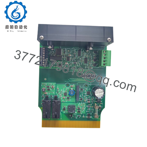
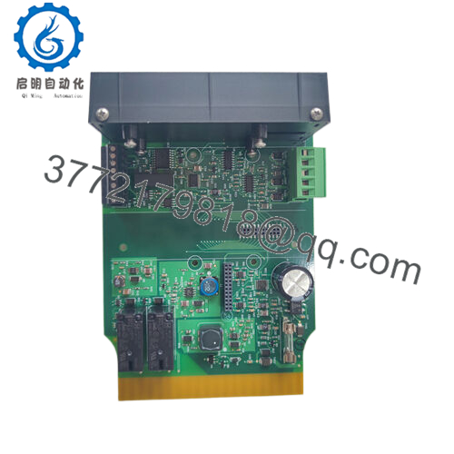
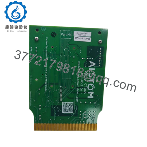
The ALSTOM 029.063 242 is a pulse amplifier PCB module used in legacy Alstom and Converteam industrial automation systems. It typically appears in turbine control racks, marine propulsion control panels, and power plant auxiliary control architectures.
Its primary role is signal conditioning—taking low-level control pulses from a controller backplane and amplifying/cleaning them for downstream actuator or control interface stages. The module is tightly integrated into proprietary rack systems, making direct substitution with modern hardware non-trivial without full system engineering validation.

- 029.063 242
5. Installation & Configuration Guide
Stage 1: Pre-Installation Preparation (10–15 min)
- ⚠️ Confirm full system shutdown (turbine or process line interlock required)
- Apply LOTO on control cabinet and verify zero energy state
- Tools required: ESD wrist strap, precision screwdriver set, multimeter, camera
- Document before removal:
- Rack slot position
- Ribbon/backplane connector orientation
- Any jumper or revision markings on PCB
- Inspect spare module for:
- Corrosion on edge connectors
- Cracked solder joints
- Burn marks near power regulation stage
Stage 2: Removing the Old Module (10–20 min)
- Open control rack front access panel
- Identify module slot and label adjacent cards
- Disconnect any secondary harnesses (if present)
- Release PCB locking ejectors carefully
- Pull module straight out—avoid flexing backplane pins
- Store removed module in anti-static bag for reference
⚠️ Do not “wiggle out” the board—edge connector damage is one of the most common irreversible failures.
Stage 3: Installing the New Module (10–20 min)
- Verify exact part number: 029.063 242 (revision matching critical)
- Inspect rack slot for dust, oxidation, or bent pins
- Align PCB with guide rails and insert evenly
- Press firmly until full backplane engagement is confirmed
- Lock ejector tabs
- Reconnect any auxiliary wiring if applicable
Self-check:
- Full seating confirmed
- No visible PCB tilt
- Locking mechanism engaged
- Connector alignment verified
Stage 4: Power-On & Testing (10–15 min)
- Energize control rack only (field loads disconnected initially)
- Check module status indicators (if present on system rack)
- Verify signal continuity using system diagnostics tools
- Confirm pulse output stability under idle conditions
- Gradually reintroduce process load
⚠️ If system enters fault state immediately, suspect:
- Backplane contact mismatch
- Incorrect module revision
- Signal timing incompatibility with controller
6. Frequently Asked Questions (FAQ)
1. What exactly does this module do?
It amplifies and conditions control pulses inside Alstom/Converteam turbine or industrial automation racks. It is part of the signal chain, not a standalone controller.
2. Is this still manufactured?
No. This is a legacy platform module. Most available units are surplus or recovered from decommissioned systems.
3. Can I replace it with a modern PLC module?
Not directly. The signal timing, backplane protocol, and electrical interface are proprietary. Replacement usually requires full system retrofit.
4. What causes failure in this card?
Most failures come from aging electrolytic components, connector oxidation, or thermal cycling stress—not logic failure.
5. Can I hot-swap it?
No. Removing it under power can destabilize the control loop and cause system trips or unsafe turbine behavior.
6. Why are there different brand markings (Alstom / Converteam)?
This module exists across multiple ownership eras (Alstom → Converteam → GE lineage), but the hardware remains largely the same.
7. Why is pricing inconsistent in the market?
Condition (tested NOS vs used), revision number, and provenance (marine vs power plant sourcing) heavily affect value.



