
 WhatsApp: +86 16626708626
 Email:
  Phone: +86 16626708626
Description
Key Technical Specifications
| Parameter | Specification Value |
| Manufacturer | Alstom |
| Model / Part Number | 029.111 890 |
| Component Category | Electronic Timing / Time-Delay Relay |
| Timing Range | Configurable multi-range selector (Refer to front scale calibration) |
| Control Operating Voltage | Rated auxiliary AC/DC supply (See unit side-plate for specific voltage) |
| Output Contacts | High-capacity timed changeover contacts (N/O, N/C configurations) |
| Contact Thermal Rating | 5 A continuous current capability |
| Repeatability Accuracy | Within ±1% of the set scale limit |
| Reset Time | Less than 50 ms upon control voltage de-energization |
| Mounting Layout | DIN rail channel or surface panel backplate mount |
| Housing Construction | High-impact, flame-retardant industrial polymer |
| Operating Temperature | −10 to +60 °C |
Product Introduction & Supply Chain Strategy
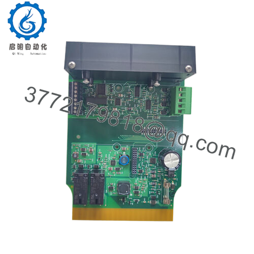
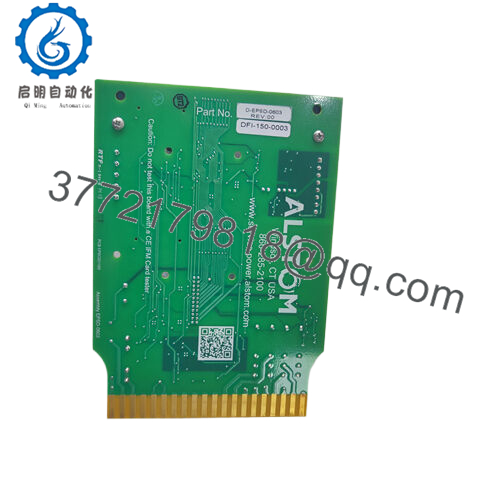
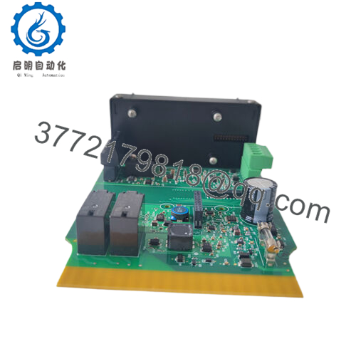
The Alstom 029.111 890 is an industrial-grade electronic timing relay designed to manage precise sequence-of-events switching logic within electrical substations, generation facilities, and automated plant control networks. This module introduces structured time delays—such as on-delay, off-delay, or pulsing intervals—into automated interlocking loops. These delays are critical for allowing voltage rails to stabilize, ensuring safety valves complete their mechanical travel, or managing multi-stage turbine starting parameters.
From a supply chain standpoint, the 029.111 890 is an essential asset categorized under strategic risk mitigation. Because automated sequencing relies heavily on precise timing steps, a drifted or dead timing relay can stall critical power restoration steps or prevent a localized breaker from tripping in order. Keeping 1–2 New Surplus units as an immediate on-site insurance policy effectively counters standard manufacturer lead time variability. This approach allows facilities to maintain operational continuity while bypassing the high failure rates and degraded capacitor profiles associated with refurbished components.

- 029.111 890
Installation & Configuration Guide
Stage 1: Pre-Installation (Prep & Safety)
- Turn off all control power distribution breakers supplying the target relay panel cubicle. Use a calibrated digital multimeter to verify the terminal blocks are completely dead.
- Fasten a grounded static-dissipative wrist strap to your wrist to safeguard the internal timing micro-components from ESD.
- Record a high-resolution photograph of the active wiring layout. Note the specific terminal assignments for input trigger power lines and output contacts.
- Review the potentiometer dial settings or DIP switch positions on the face of the legacy unit and match those parameters onto the new module.
Stage 2: Removal
- Unfasten the screw terminals on the wire connection block and pull the wire lugs away from the housing tracking.
- Use a small flat-head screwdriver to release the bottom tension clip holding the relay frame to the DIN rail, or back out the panel mounting fasteners.
- Smoothly pull the unit straight off the mounting rail without twisting, which could damage adjacent wiring bundles.
- Clean the local mounting space to remove accumulated dust, grime, or metallic residue.
Stage 3: Installation (Clone & Seat)
- Snap the new Alstom 029.111 890 onto the 35 mm DIN rail or align it with the surface panel bolt holes. Verify that the unit clicks securely into place.
- Adjust the front potentiometers or select the correct time-multiplier scale using a fine adjustment tool to mirror the exact delay window needed by your facility’s operational schematic.
- Secure the labeled control and contact wires back onto their assigned terminals. Tighten the terminal screws to a verified torque rating of 0.5 to 0.7 Nm.
Stage 4: Power-On & Testing
- Re-apply the auxiliary control voltage. Ensure the primary power status LED illuminates steadily without blinking or throwing immediate system fault signs.
- Initiate a system test cycle to trigger the timing loop. Use a stopwatch or an inline data logger to verify that the relay transitions at the designated time interval.
- Measure contact resistance across the timed contacts when closed, ensuring a clean, low-impedance connection path.
- Run the module through 3 consecutive automatic cycles to verify the timing accuracy and eliminate the risk of early out-of-box hardware failure.
Firmware/Software Versions & Upgrade Notes
The Alstom 029.111 890 relies on internal analog-to-digital hardware timers or dedicated embedded microchips to execute its timing sequences. It does not utilize downloadable software applications or field-upgradeable firmware operating systems.
- Hardware Part Integrity: Timing profiles and parameter behaviors are fixed properties determined by the specific “890” model suffix configuration.
- Replacement Precaution: Avoid mixing models within this family even if they share an identical physical shell layout. Internal changes to voltage sensing tolerances or input-to-output terminal assignments can disrupt interlocking loops and cause the system to drop out unexpectedly.
Frequently Asked Questions (FAQ)
Is this Alstom 029.111 890 unit brand new, or has it been pulled from an old panel?
This timing relay is a guaranteed 100% Brand New Surplus unit. It has never been deployed in an active field panel, used in regular factory production, or subjected to industrial thermal stress. It arrives in pristine factory condition with clean terminal surfaces, a clear front scale face, and unmarred housing plastics.
Why should I choose a New Surplus unit over a cheaper refurbished timing relay?
Refurbished timing modules carry a high risk of timing drift. The internal RC timing circuits and smoothing logic rely heavily on internal capacitors, which dry out, degrade, and shift in value over years of exposure to hot electrical enclosures. A refurbished unit may look clean but can cause erratic timing delays that disrupt sequence-of-events logic. Purchasing a verified New Surplus part ensures zero-hour operational capacity and predictable timing control.
Can this timing module be configured for both On-Delay and Off-Delay operation?
The specific operational mode (On-Delay, Off-Delay, or Interval Timing) depends on the exact internal wiring diagram designated by the 890 suffix configuration. Check the schematic stamped on the side panel of the unit housing to verify that the logic function matches your plant’s application requirements.
What should I do if the time delay does not match the front dial position precisely?
Small variances can sometimes occur due to extreme ambient panel temperatures. However, if the time delay drifts significantly, verify that the incoming auxiliary control voltage is stable and within the +10% / −15% tolerances specified on the unit rating plate. Unstable control power can compromise the accuracy of internal electronic timing sweeps.
Does this module require a battery backup to retain its configured time settings?
No. The time delay settings are adjusted mechanically via physical front panel dials or internal hardware jumpers. Because these values are set through static components, the unit does not require an internal backup battery and will retain its calibrated settings indefinitely through total power losses.
What type of warranty coverage applies to this surplus asset?
This Alstom 029.111 890 timing relay is backed by a full 1-year elite warranty starting from the day of delivery. If any operational deviations or physical hardware failures occur under standard plant conditions within this timeframe, the asset is fully covered.



