
 WhatsApp: +86 16626708626
 Email:
  Phone: +86 16626708626
Description
Key Technical Specifications
| Parameter | Specification |
| Manufacturer | Alstom |
| Part Number | 029.362754 |
| Component Type | Auxiliary Relay / Interface Circuit Board |
| Application | Power Transmission, Substation Protection & Railway Automation |
| Mounting Format | Rack-mount / Modular Protection Enclosure sub-assembly |
| Contact Configuration | Heavy-duty dry contacts for high-current trip circuits |
| Dielectric Strength | \ge 2.0 kV RMS between coil and contact terminals |
| Operating Temperature | -20^\circC to +60^\circC |
Product Introduction & Supply Chain Strategy
The Alstom 029.362754 is a specialized auxiliary relay and interface component designed for electrical protection racks, high-voltage substations, and industrial power distribution panels. It acts as an isolation and multiplication stage, translating low-voltage control signals from main numerical relays (such as MiCOM or AGiLE series) into high-capacity switching actions that operate trip coils on medium- and high-voltage circuit breakers.
When an auxiliary relay card fails due to contact degradation or component breakdown, trip loops can become unmonitored or non-functional, risking severe equipment damage during power grid faults. Maintaining verified OEM surplus 029.362754 modules in critical spare inventory prevents prolonged downtime during routine maintenance or emergency substation repairs.
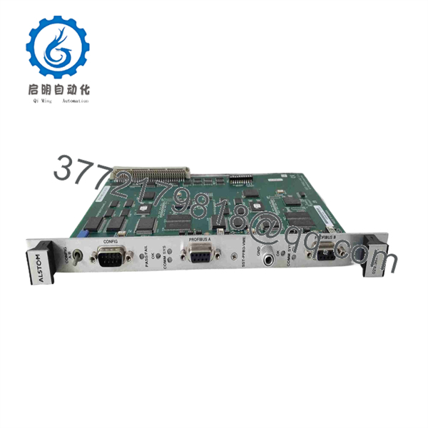
029.362754
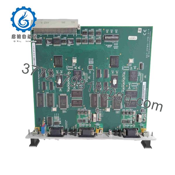
029.362754
Installation & Maintenance Steps
1.Stage 1: Pre-Installation & De-Energization:Power Isolation & Safety Prep.
Isolate all incoming AC/DC auxiliary supplies and CT/VT circuit inputs feeding the relay rack. Ensure all breaker trip coils and lock-out circuits are isolated to prevent accidental tripping during hardware replacement.
2.Stage 2: Extraction:Module Removal.
Disengage retaining screws or rack locking tabs. Carefully extract the existing 029.362754 card straight out from the backplane connector to avoid bending backplane pins.
3.Stage 3: Installation & Seating:Mechanical Insertion.
Inspect the edge connector and pin paths on the replacement 029.362754 module. Slide the board smoothly along the card guide slots until fully seated into the backplane socket, then secure all retaining hardware.
4.Stage 4: Secondary Injection & Trip Testing:Functional Verification.
Re-apply DC control power. Perform a secondary injection test to confirm relay pick-up levels, timing specs, and contact continuity before restoring the breaker trip outputs to service.
Frequently Asked Questions (FAQ)
Q: Where is the Alstom 029.362754 module typically deployed?
A: It is primarily used in power generation plants, transmission substations, and heavy rail electrification panels that utilize Alstom protection schemes.
Q: Can this component be installed while the protection rack is energized?
A: No. Always de-energize and lock out all control and trip circuits before removing or inserting internal relay boards to avoid arc flashes or false breaker trips.
Q: Does this module require software programming or configuration?
A: The 029.362754 operates as a hardware-level electro-mechanical or solid-state interface board and typically does not require firmware flashing; however, terminal jumpers must match the original board configuration.



