
 WhatsApp: +86 16626708626
 Email:
  Phone: +86 16626708626
Description
3. Key Technical Specifications
- Manufacturer: Alstom
- Model: 20X4496G
- Product Type: Power Conversion PCB Card
- Application: Industrial power conversion systems and drive control equipment
- Main Function: Power semiconductor control interface / converter control board
- Technology: IGBT power electronics control interface (configuration dependent)
- Compatible Systems: Alstom Power Conversion equipment
- Board Design: Industrial PCB assembly
- Installation Type: Cabinet/rack-mounted control electronics
- Weight: Approx. 14.12 kg (reported for listed unit configuration)
- Revision Variants: 20X4496 series may include different PCB revisions; verify suffix before installation
- Service Status: Legacy spare component; availability depends on remaining inventory
4. Product Introduction
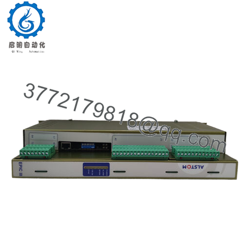
The Alstom 20X4496G is a Power Conversion PCB card used in Alstom industrial power conversion equipment. It functions as a control electronics module within converter systems, supporting applications in power systems, industrial automation, and drive-related equipment.
This legacy board is mainly supplied for maintenance replacement where existing Alstom converter hardware remains operational. Before installation, verify PCB revision, converter model, connector layout, and existing control configuration.

- 20X4496G
5. Installation & Configuration Guide
Stage 1: Pre-Installation Preparation (Approx. 15 minutes)
⚠️ Safety First
- Notify operations about the maintenance activity.
- Confirm the converter system is stopped and isolated.
- Apply lockout/tagout procedures.
- Disconnect auxiliary and main power sources.
- Wait for DC bus discharge according to equipment requirements.
Tools Required
- ESD wrist strap
- PH1 screwdriver
- Digital multimeter
- Wire labels
- Smartphone/camera for documentation
Data Backup
- Record the existing board position.
- Photograph:
- PCB label
- Connector locations
- Jumper/switch settings
- Adjacent control boards
- Document:
- Converter configuration
- Alarm history
- Existing parameters
Stage 2: Removing the Old Module (Approx. 15 minutes)
- Remove cabinet covers following site procedures.
- Verify zero voltage condition with a multimeter.
- Disconnect board connectors carefully.
- Release mounting hardware.
- Remove the PCB straight out to avoid connector damage.
⚠️ Inspection Note
- Check backplane connectors for contamination.
- Inspect pins for bending or oxidation.
- Keep the removed 20X4496G for reference until commissioning is complete.
Stage 3: Installing the New Module (Approx. 15 minutes)
- Wear ESD protection before handling the replacement PCB.
- Verify:
- Exact part number: 20X4496G
- PCB revision
- Connector condition
Configuration Clone (Critical)
- Match the original board position.
- Copy all jumper and hardware configuration settings.
- Confirm connector orientation.
- Insert the PCB into the correct slot.
- Secure mounting screws.
- Reconnect all plugs firmly.
Self Checklist
[ ] Correct PCB revision verified
[ ] Connectors fully seated
[ ] Mounting hardware secured
[ ] Configuration copied
[ ] Wiring checked
Stage 4: Power-On & Testing (Approx. 30 minutes)
Pre-Power Check
- Verify insulation condition.
- Check DC supply rails.
- Confirm no short circuit exists.
Power-On Steps
- Energize control power only.
- Check board indicators if available.
- Verify converter controller recognition.
- Monitor diagnostic alarms.
- Perform low-power functional testing.
- Confirm converter operation under controlled load.
⚠️ Troubleshooting Note
- No startup: Check board revision compatibility and power supply rails.
- Converter fault after replacement: Verify gate drive connections and parameter compatibility.
- Intermittent alarms: Inspect connectors and grounding.
6. Frequently Asked Questions (FAQ)
Q1: Can I hot-swap the Alstom 20X4496G PCB card?
No. Do not remove or install this board under energized conditions. Power conversion equipment contains high-energy circuits, and removing control PCBs while powered can damage electronics or create unsafe operating conditions.
Q2: Is the Alstom 20X4496G obsolete?
The 20X4496G is a legacy Alstom Power Conversion spare component. Availability is typically based on remaining industrial inventory and maintenance stock. Alstom provides lifecycle and parts support channels for some legacy equipment.
Q3: Is the 20X4496G new original or refurbished?
Confirm the exact supply condition before purchase.
Typical conditions:
- New Original / New Surplus: Unused OEM inventory.
- Factory Sealed: Original packaging condition.
- Refurbished (tested): Previously installed board inspected and function tested.
Request PCB photos, serial markings, and test records for critical applications.
Q4: Is 20X4496G the same as 20X4496G4?
Not necessarily. The 20X4496 family includes revision variations. Some listings reference related versions such as 20X4496G4 or other revisions. Always match the complete part marking and PCB revision before installation.
Q5: What should I check before replacing this PCB card?
Verify:
- Exact Alstom part number
- PCB revision
- Converter model
- Connector arrangement
- Existing control parameters
- Firmware/software compatibility if applicable
A similar-looking power electronics board may not be electrically interchangeable.
Q6: Why is surplus pricing different from OEM pricing?
Legacy automation and power conversion components are often traded through maintenance inventories. Price depends on condition, testing history, packaging, and remaining availability.
Q7: What inspection should be completed before field installation?
Recommended inspection sequence:
- Part number verification
- Visual inspection for corrosion, cracks, or repair marks
- Connector inspection
- Electrical parameter checks
- Power-up diagnostic test
- Functional converter test
For critical converter systems, request a test report before installation.



