
 WhatsApp: +86 16626708626
 Email:
  Phone: +86 16626708626
Description
Key Technical Specifications
| Parameter | Specification / Value |
| Manufacturer | Alstom |
| Part Number | AL129A |
| Product Series | Power Control & Turbine Governing Series |
| System Compatibility | Alstom DCS / Turbine Protection & Logic Panels |
| Supply Voltage | 24 V DC / 110 V DC (Nominal system bus voltages) |
| Power Consumption | Approx. 8 W |
| I/O Interfaces | Isolated digital logic inputs, relay driver outputs, analog feedback loops |
| Operating Temperature | 0 to +60 °C (+32 to +140 °F) |
| Form Factor / Mount | Eurocard format / Sub-rack mounting chassis |
| Weight | Approx. 0.50 kg (1.10 lbs) |
Product Introduction & Supply Chain Strategy
The Alstom AL129A is a specialized logic interface and signal processing card designed for heavy-duty power plant controls, generator protection systems, and turbine governing platforms. Built to meet stringent utility-grade operational standards, this circuit board conditions discrete field inputs, executes deterministic interlocking logic, and drives control relays for critical power infrastructure.
Sourcing the Alstom AL129A as New Surplus provides plant managers with a vital hedge against forced downtime. Because legacy Alstom control lines are largely discontinued by original manufacturer channels, finding unused original units prevents the risks inherent in secondhand or degraded parts. Keeping a verified AL129A in buffer stock drastically reduces your Total Cost of Ownership (TCO) by avoiding millions in lost power generation revenue during emergency trips.
Installation & Configuration Guide
1.Pre-Installation & Safety Preparation:De-energize sub-rack power and take ESD precautions.
- De-energize all primary and auxiliary control power feeds to the Alstom card rack.
- Put on a grounded ESD wrist strap connected to the enclosure frame to prevent static discharge to onboard logic ICs.
- Document and photograph all DIP switch banks, jumper block configurations, and card slot addresses on the existing board.
2.Card Extraction & Slot Inspection:
- Loosen the top and bottom captive retaining screws on the card faceplate.
- Unlatch the ejector handles smoothly to unseat the rear edge connector from the backplane.
- Slide the card out along the card guide rails, avoiding twisting or lateral stress on the backplane pins.
3.Hardware Alignment & Card Insertion:
- Configure all DIP switches and jumper headers on the replacement AL129A board to match the original card configuration.
- Align the replacement module card edges with the sub-rack guide rails and slide it in carefully.
- Press the card faceplate firmly until the backplane connectors fully mate, then secure the retaining screws.
4.Power-On Validation & System Synchronization:
- Reapply system power and observe the front panel diagnostic LEDs (POWER, RUN, FAULT).
- Verify communication and I/O status from the main turbine controller or DCS engineering station.
- Perform a simulated logic test on input channels to confirm relay tripping and feedback signaling.
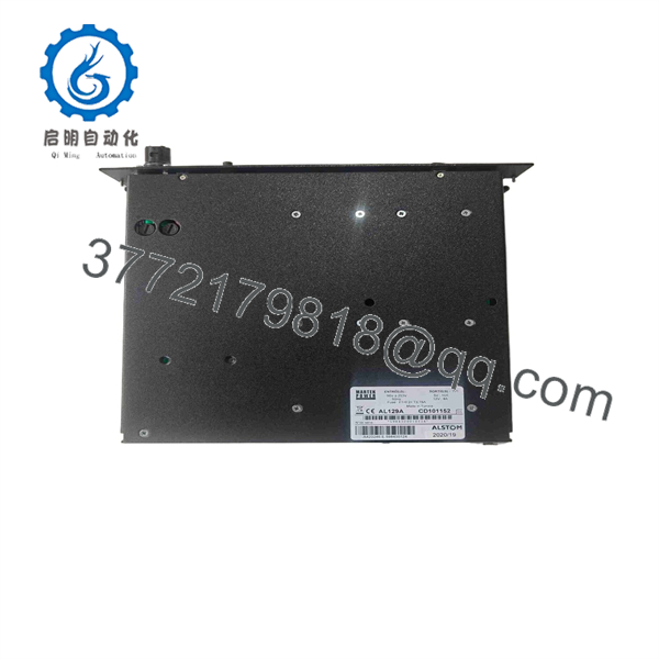
AL129A
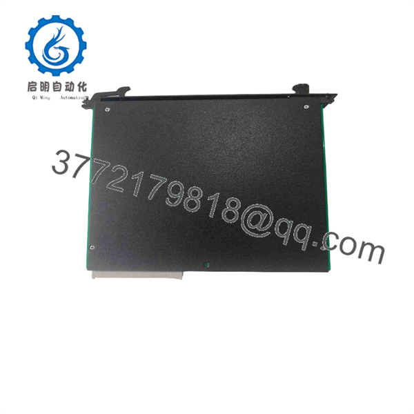
AL129A
Firmware/Software Versions & Upgrade Notes
- Hardware Revision Verification: Check the board revision and suffix numbers on the AL129A PCB. Ensuring exact revision parity prevents signal scaling errors or pinout incompatibilities on backplane busses.
- Jumper & DIP Switch Mirroring: Operational parameters, gain settings, and bus address definitions are often configured via physical jumper blocks. Verify that all jumpers match factory schematics before energizing.
- System Parameter Loading: Logic execution is tied to the main rack processor; ensure the controller firmware version supports this board revision prior to startup.
Frequently Asked Questions (FAQ)
Is this Alstom card brand new or harvested from a decommissioned power plant?
This card is New Surplus (Original New). It is unissued, unused OEM stock obtained from canceled plant projects or strategic spare reserves. It has never been installed in an active control panel or subjected to thermal cycling.
Why choose New Surplus over a lower-cost refurbished Alstom board?
Refurbished power-plant electronics carry high risks of hidden component degradation. Thermal stress in turbine control cabinets ages capacitors, optocouplers, and solder connections over time. A failure in a refurbished logic card can trip a turbine or generator, resulting in severe downtime costs. New Surplus provides factory-fresh component life and 100% operational confidence.
Is the board a direct drop-in replacement?
Yes, provided you replicate the physical jumper blocks and DIP switch settings from your original module. No cabinet rewiring or backplane modifications are required.
Can I replace this module while the system is under load?
Hot-swapping logic cards in legacy power control systems is not recommended unless specifically noted in your system manual. Removing a board under power can trigger backplane communication faults or trip protective lockout relays. Always de-energize the target rack before replacement.
What warranty is provided with this surplus component?
We back this unit with a 1-Year Comprehensive Replacement Warranty. Every board undergoes visual inspection and backplane power-rail testing prior to dispatch.



