
 WhatsApp: +86 16626708626
 Email:
  Phone: +86 16626708626
Description
3. Key Technical Specifications
- Module Type: Lamp & meter indication PCB board
- Application: Power plants, substations, industrial control panels
- Function: Real-time electrical parameter display and system status indication
- Display Interface: Analog meters + indicator lamps (panel-mounted)
- Input Type: Electrical measurement signals (voltage/current sensing circuits)
- Measurement Range: Typically configurable (e.g., 0–10 mA DC meter loops in many revisions)
- Power Supply: Panel-derived DC supply (system-specific)
- Mounting: Front-panel integration inside control cabinets
- Construction: Lightweight PCB assembly (~80–180 g depending on revision)
- Operating Environment: Industrial electrical rooms, turbine control panels, substations
- Thermal Design: Passive operation (no active cooling)
- EMI Resistance: Designed for high electrical noise environments
- Failure Modes: Lamp burnout, meter coil degradation, connector oxidation, aged resistors/capacitors
- Revision Sensitivity: Medium (mechanical fit consistent, calibration varies by variant)
4. Product Introduction
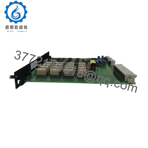
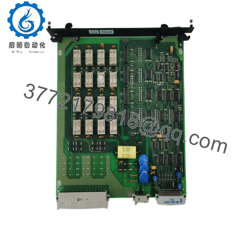
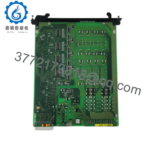
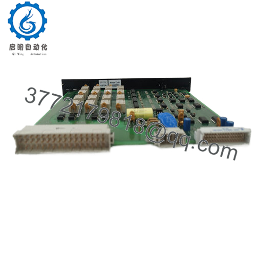
The ALSTOM D-984-0721 is a lamp and meter board used in legacy Alstom industrial control and power distribution panels. It provides real-time visual indication of electrical parameters such as current and system status through analog meters and indicator lamps.
It is widely deployed in power generation plants and heavy industrial electrical cabinets where local operator visibility of system health is required. The module is not a controller; it functions strictly as an interface and indication layer within a larger control architecture.

- D-984-0721
5. Installation & Configuration Guide
Stage 1: Pre-Installation Preparation (10–15 min)
- ⚠️ Confirm panel is fully de-energized (critical for meter circuits)
- Apply Lockout/Tagout (LOTO) on incoming supply feeders
- Verify zero voltage across meter input terminals using calibrated multimeter
- Required tools:
- ESD wrist strap
- Small flathead/Phillips screwdriver
- Multimeter
- Labeling tape
- Camera for wiring documentation
- Document before removal:
- Wire termination points on meter inputs
- Lamp wiring polarity (if DC indicators used)
- Panel cutout orientation
Stage 2: Removing the Old Module (10–20 min)
- Open control panel door and access front instrumentation board
- Label all meter and lamp wiring
- Disconnect signal leads carefully (avoid pulling on terminals)
- Remove mounting screws or retaining clips
- Extract board straight out of panel housing
- Inspect connectors and wiring for heat discoloration
⚠️ Avoid forcing meter needles or lamp sockets during removal—mechanical damage is common and irreversible.
Stage 3: Installing the New Module (10–20 min)
- Verify exact model match: D-984-0721
- Check panel cutout alignment and mounting compatibility
- Secure board into mounting position
- Reconnect wiring according to labeled documentation
- Tighten terminal screws to avoid vibration loosening
- Confirm lamp polarity and meter wiring correctness
Self-check:
- All terminals secured
- Wiring matches original mapping
- No loose mechanical mounting
- No pinched cables behind panel
Stage 4: Power-On & Testing (10–15 min)
- Energize control panel gradually
- Observe lamp indicators for correct status response
- Verify meter deflection under known load conditions
- Cross-check readings with external calibrated instrument
- Confirm stable operation for 10–15 minutes under load
⚠️ If meters show zero or full-scale deflection:
- Check wiring polarity reversal
- Inspect signal loop continuity
- Verify resistor calibration network integrity
6. Frequently Asked Questions (FAQ)
1. What is the ALSTOM D-984-0721 used for?
It is a lamp and meter indication board used to visually display electrical parameters and system status in industrial control panels.
2. Is this still manufactured?
No. It is a discontinued legacy component. Most available units are surplus or refurbished stock.
3. Is it a control module or a display module?
It is strictly a display/indication module. It does not perform control logic or automation functions.
4. What commonly fails in this board?
Typical failures include burnt indicator lamps, aging analog meter movement, and degraded passive components in signal conditioning circuits.
5. Can it be hot-swapped?
No. It must be de-energized before removal to prevent meter damage and electrical hazard.
6. Are all D-984-0721 units identical?
No. Mechanical layout is similar, but meter ranges, lamp configurations, and revision codes may vary.
7. Why is it still used in modern plants?
Many legacy power and industrial control panels remain in service for decades, requiring continued support for indicator and metering subsystems.



