
 WhatsApp: +86 16626708626
 Email:
  Phone: +86 16626708626
Description
Key Technical Specifications
- Manufacturer: ALSTOM Electrical Machines Ltd.; GECOSTAT legacy product line
- Full Model: FV223-M2
- Base Type: FV223
- Form / Revision: M2
- Product Type: Exciter diode failure detector
- Product Family: Gecostat generator excitation and AVR equipment
- Primary Function: Monitors the rotating rectifier diode bridge in a brushless synchronous-generator excitation system for failed excitation diodes
- Installation Role: Provides fault indication or alarm/trip interface to the generator excitation and protection system
- Typical Application: Turbo-generator, hydro-generator, synchronous-motor, and industrial generator excitation cabinets
- Mounting: Verify against the original unit; available listings identify a plug-in electronic module format rather than a generic field instrument
- Weight: Approximately 8 lb / 3.6 kg in one distributor listing; verify the physical unit because listing weights may include packaging or form-specific hardware
- Dimensions: One used-stock reference reports approximately 9 × 12 × 3 in; verify all dimensions from the actual module and excitation-panel drawing
- Supply, Signal, and Relay Ratings: Confirm from the original FV223-M2 nameplate, Gecostat wiring schematic, and generator excitation documentation before connecting power or field signals
- Lifecycle Status: Discontinued by manufacturer; normally sourced as new-surplus, tested used, repair-exchange, or refurbishment inventory
Available inventory references consistently identify the FV223-M2 as an ALSTOM/GECOSTAT exciter diode failure detector, Form M2, for generator excitation equipment. A distributor categorizes it as discontinued, while a used-unit listing reports Form M2 and an approximately 8 lb weight. Public reseller claims about detailed electrical ratings conflict or lack OEM validation, so field connection data must come from the original Gecostat documentation and installed cabinet drawings.
Product Introduction
The ALSTOM FV223-M2 is a Gecostat exciter diode failure detector used in brushless generator excitation systems. It monitors the rotating rectifier assembly for diode faults that can create abnormal excitation ripple, reduced field performance, excessive heating, unstable generator voltage, and progressive damage to the rotating exciter or main rotor.
This is a protection and monitoring module for an existing Gecostat excitation cabinet, not a universal AVR or a general-purpose drive. Match the FV223-M2 Form M2 label, rack position, wiring diagram, exciter type, diode-monitoring connections, alarm/trip logic, and generator-specific settings before ordering. Incorrect substitution can produce nuisance trips or leave a real rotating-diode fault undetected.
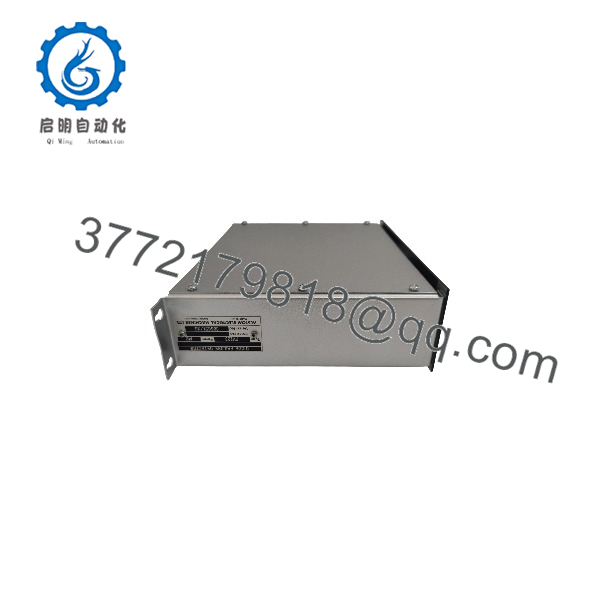
FV223-M2
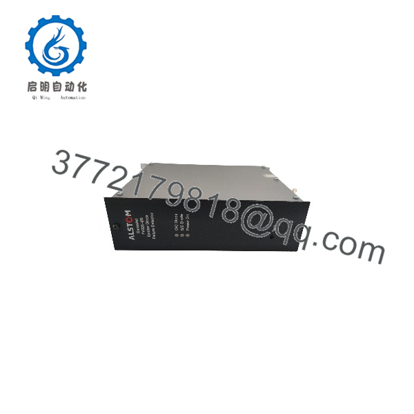
FV223-M2
Troubleshooting Quick Reference
| Symptom | Possible Cause | Relevance to This Part | Quick Check Method | Recommendation |
|---|---|---|---|---|
| Diode-failure alarm activates during normal generator operation | Actual rotating rectifier diode fault, loose exciter connection, abnormal excitation waveform, -M2 sensing circuit fault | ✅ Medium to high | Review excitation-system alarms and generator operating trends; inspect rotating-diode condition only during an approved outage; compare diode tests and excitation ripple against OEM procedure | Treat the alarm as valid until rotating-diode health and sensing wiring are proven |
| Generator voltage fluctuates or AVR response is unstable | AVR tuning issue, excitation transformer problem, sensing circuit fault, load change, rotating diode defect | ❌ Usually low to medium | Check AVR diagnostics, PT/CT sensing, excitation current, load changes, and waveform/ripple measurements using approved test equipment | Diagnose AVR and excitation system first; -M2 does not regulate voltage directly |
| Alarm remains active immediately after startup | Open or shorted monitor wiring, failed detector module, wrong rack connection, configuration mismatch, existing diode defect | ✅ High | Confirm module power and seating; inspect sensing connectors and wiring against the Gecostat drawing; verify relay output state and alarm reset conditions | Verify wiring and actual diode condition before repla |
| No diode alarm during a known or simulated test condition | Failed module, failed alarm relay, open output wiring, disabled alarm circuit, incorrect test procedure | ✅ High | Perform only the OEM-approved test or simulated test method; verify detector output relay, alarm input, and annunciator circuit | Do not inject signals or defeat excitation protection without an approved procedure |
| Module has no LED or no apparent activity | Missing control supply, blown cabinet fuse, loose rack connection, fa | ✅ Medium | Measure the documented control supply at the module/rack terminals; check panel fuses, backplane contacts, and cabinet power | Confirm correct supply and rack integrity before replacement |
| Alarm occurs only at high load or field current | Marginal rotating diode, heat-sensitive connection, increased excitation demand, wiring insulation breakdown | ✅ Medium to high | Trend alarm timing against generator MW/MVAR, field current, temperature, and excitation voltage; schedule outage inspection if the pattern repeats | Plan a controlled rotating-rectifier inspection. Do not dismiss load-dependent alarms |
| Replacement module produces immediate alarm | Wrong form/revision, incompatible calibration, incorrect wiring, unreset latching circuit, pre-existing field fault | ✅ High | Compare full label, Form M2, terminal assignments, rack position, plug-in orientation, and alarm reset logic against the old unit | Do not modify wiring to suppress the alarm. Confirm correct hardware and investigate the field condition |
| Nuisance alarm after maintenance | Sensing lead swapped, connector not fully seated, shielding/grounding changed, incorrect terminal reconnection | ✅ Medium | Compare every sensing lead with pre-maintenance photos and schematic; inspect connector pins, shield termination, and cable routing | Correct field wiring and perform an approved functional test before return to service |
| Visible burnt marks or damaged connectors | Surge event, insulation failure, poor rack contact, overvoltage, contamination | ✅ High | Isolate control power; inspect module, rack socket, terminal block, fuses, and adjacent excitation equipment | Replace damaged parts and determine the upstream fault cause before re-energizing |
Field warning: A diode-failure detector alarm is not a nuisance by default. One failed rotating rectifier diode can increase ripple and thermal stress in the remaining diode bridge. Repeatedly resetting the alarm without a planned exciter inspection is how a manageable repair becomes a generator outage.
❗ Do not attempt rotating-diode testing on energized equipment. Brushless-excitation systems contain rotating components and potentially hazardous excitation voltages. Shut down, isolate, lock out/tag out, discharge stored energy, and follow the generator OEM’s approved inspection procedure.
If you need help, provide qualified excitation-service personnel with a label photo, Gecostat cabinet drawings, alarm history, generator load and field-current trends, excitation-system fault logs, wiring photographs, and rotating-diode test results from the approved maintenance procedure.
Frequently Asked Questions (FAQ)
What is AL?
The AL is a GECOSTAT exciter diode failure detector for generator excitation systems. It monitors the rotating rectifier diode assembly in a brushless excitation system and provides fault detection for the associated excitation/protection controls.
an automatic voltage regulator?
No. It is not the primary automatic voltage regulator. The AVR controls generator excitation to maintain terminal voltage or reactive-power targets. is a monitoring/protection module that detects conditions associated with failed rotating-exciter diodes. It supports the excitation system but does not replace the full AVR function.
What does the M2 suffix mean?
M2 identifies the Form M2 version of the detector. It matters because legacy Gecostat modules can differ by form, connector arrangement, terminal assignment, sensing method, relay logic, calibration, or cabinet interface. Match the complete marking rather than ordering by the base number alone.
Is still manufactured?
No. Distributor records iden as discontinued. It is normally available only through legacy-spare channels, including new-surplus, tested used, repair-exchange, or refurbishment inventory. Confirm actual stock, condition, lead time, test status, and warranty before committing to an outage plan.
Can I rep with another generator excitation module?
Not automatically. A module can appear physically similar yet have different diode-sensing inputs, supply requirements, alarm/trip contact configuration, rack connections, calibration, or generator compatibility. Use the original Gecostat schematic, full module label, and generator excitation system documentation to verify an exact replacement.
Why is the detector alarming if the generator is still producing normal voltage?
A generator can continue producing acceptable voltage with a degraded rotating diode bridge, especially at light load. A single open or shorted diode may not immediately cause a voltage collapse, but it can increase excitation ripple, uneven diode loading, rotor heating, and stress on the remaining diodes. Review field current, harmonic/ripple data where available, and alarm history. Schedule an approved inspection rather than waiting for a forced outage.
Can I test by disconnecting diode-monitoring wires while the generator is online?
No. Do not create or simulate an excitation fault on an online generator unless the generator OEM and plant operating procedure explicitly authorize a controlled test. Disconnecting or disturbing sensing wiring can trigger an unnecessary trip, mask a real problem, or expose personnel to hazardous voltage. Use only the documented excitation-system functional test.
Why is sur inventory less expensive than an OEM excitation retrofit?
Surplus inventory supports repair of an existing Gecostat cabinet without redesigning the full excitation and protection system. It costs less upfront because it is legacy stock, not a current supported platform. However, it does not eliminate obsolescence risk. For critical units, keep a verified spare, preserve drawings and settings, and develop a planned excitation-control modernization strategy.



