
 WhatsApp: +86 16626708626
 Email:
  Phone: +86 16626708626
Description
3. Key Technical Specifications
| Parameter | Value |
| Manufacturer | ALSTOM |
| Model Number | GDB100-4401 |
| Product Line | ALSPA Drives & Controls |
| Maximum DC Current | 100 A |
| Maximum Duty Cycle | 25% |
| DC Braking Voltage Threshold | 755 V DC |
| DC Withstand Voltage | 800 V DC |
| Auxiliary Supply Voltage | 22 V to 55 V DC |
| Auxiliary Power Rating | 10 W |
| Module Net Weight | 7.40 kg (16.31 lbs) |
| Cooling Profile | Natural convection / chassis heat dissipation |
| Primary System Role | Regenerative energy absorption and bus link protection |
4. Product Introduction & Supply Chain Strategy
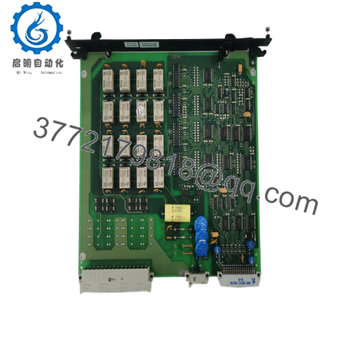
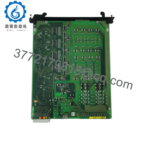
The ALSTOM GDB100-4401 is a high-performance dynamic brake control unit engineered for the heritage ALSPA drive architecture. When heavy industrial motors experience rapid deceleration, high inertial overhauling loads, or sudden stops, they reverse roles and act as electrical generators. The GDB100-4401 continuously monitors the drive’s intermediate circuit, safely activating at a 755 V DC threshold to channel this dangerous, regenerative energy into external braking resistors, limiting maximum current to 100 A. This automated chopper switching cycle keeps the internal DC bus well below its 800 V DC withstand limit, eliminating overvoltage trip incidents in heavy industrial processing, marine propulsion, and crane control loops.
From an operational risk management stance, choosing this specific unit as a New Surplus asset provides significant protection for capital equipment. Because the ALSPA drive series has been formally discontinued, facilities running these assets face extreme vulnerability to inventory stock-outs. Refurbished alternative options carry high risk because they use pre-stressed power electronics, which are prone to sudden thermal fatigue under repeated 100 A braking sequences. Sourcing this verified New Surplus control module ensures original gate-drive firing precision, controls Total Cost of Ownership (TCO), and protects against secondary hardware damage across the primary drive inverter backplane.

- GDB100-4401
5. Installation & Configuration Guide
Stage 1: Pre-Installation (Prep & Safety)
- Disconnect the primary AC power supply to the entire variable speed drive. Isolate all external auxiliary feeds and apply comprehensive lock-out/tag-out (LOTO) safety measures.
- Wait a minimum of 20 minutes for the internal DC bus capacitors to completely discharge below a safe 50 V limit. Verify zero voltage at the test points using a certified digital multimeter before touching components.
- Attach a grounded electrostatic discharge (ESD) wrist strap to the chassis ground frame to safeguard internal tracking logic from static damage.
- Take clear, high-resolution photographs of all heavy-gauge DC bus links, resistor wiring arrays, and auxiliary control lines on the old module.
Stage 2: Removal
- Unbolt the high-voltage DC bus terminals and external braking resistor cable assemblies from the power faceplate.
- Disconnect the low-voltage auxiliary connector supplying the 22 V to 55 V DC control rail.
- Loosen the primary chassis mounting bolts securing the 7.40 kg unit to the internal backplate. Lift the module straight out firmly to avoid rubbing or scraping adjacent components.
Stage 3: Installation (Clone & Seat)
- Verify that all hardware revision switch configurations on the New Surplus GDB100-4401 match the old card exactly.
- Mount the unit securely onto the enclosure sub-panel, tightening the main mounting bolts to factory specifications to ensure a solid thermal interface with the backplate.
- Reattach the high-power DC input links and resistor terminals, verifying that torque levels conform strictly to OEM electrical installation specs to prevent hot spots.
- Plug the auxiliary control harness into the designated low-voltage terminal port.
Stage 4: Power-On & Testing
- Re-energize the low-voltage auxiliary logic feed and verify that the 10 W control loop initializes with no internal errors.
- Turn on the primary drive main input circuit and monitor the standby DC bus link voltage to ensure it stabilizes well below the 755 V DC threshold.
- Perform a controlled deceleration sequence with an uncoupled motor, checking that the module accurately switches the brake circuit without throwing overvoltage faults on the primary controller.
6. Firmware/Software Versions & Upgrade Notes
The ALSTOM GDB100-4401 functions primarily as a hardwired, high-speed hardware comparator module with integrated switching logic. Consequently, it does not require conventional flash firmware uploads or software field modifications.
However, critical gate-drive timing parameters and tracking speed responses are linked directly to the physical hardware revision level—such as Rev 0005. Mixing different hardware revisions within parallel-connected drive systems or multi-axis braking arrays can cause uneven current sharing and premature circuit failure. Before placing this module into service, ensure that the revision number aligns perfectly with your existing drive controller topology and configuration drawings.
7. Frequently Asked Questions (FAQ)
- Why is this New Surplus module priced higher than refurbished versions found online?
Our pricing reflects the rarity and verified condition of entirely unused, clean OEM surplus inventory. Refurbished braking modules are frequently exposed to heavy thermal cycling and high-current stress during their previous service lives, which naturally degrades internal components. This New Surplus board eliminates those risks, offering direct drop-in reliability that safeguards your system from unexpected production breakdowns.
- Does the GDB100-4401 contain internal braking resistors?
No. This module serves exclusively as the active dynamic braking chopper controller. It regulates the switching circuit that manages regenerative power distribution, but it must be wired directly to an external, appropriately rated industrial braking resistor array to dissipate the generated energy as heat.
- What happens if my drive’s auxiliary control voltage drops below 22 V DC?
The auxiliary control port requires a steady 22 V to 55 V DC input at a 10 W power rating to drive the internal comparison logic and gate-firing circuits. If this voltage drops below the 22 V threshold, the module will fail to engage the braking circuit during a regeneration event, potentially triggering a drive overvoltage trip.
- Can this brake unit be repaired or adjusted in the field if it triggers too early?
The 755 V DC braking voltage activation point and the 800 V DC maximum limit are calibrated at the factory to protect standard ALSPA drive bus components. Field adjustments are not recommended, as altering these parameters can lead to unintended component damage or compromised safety interlocks.
- Is this specific ALSTOM drive component still supported by the OEM?
No. The ALSPA drive line and its related sub-assemblies are fully obsolete. Replacement units are no longer produced by the original manufacturer, making verified New Surplus inventory the most reliable option for keeping operational production systems online.
- What type of warranty covers this replacement module?
We provide a solid 1-year comprehensive replacement warranty starting from the date of purchase. This warranty guarantees that the module is completely free from long-term storage defects and will drop into your existing system with full operational integrity.



