
 WhatsApp: +86 16626708626
 Email:
  Phone: +86 16626708626
Description
Key Technical Specifications
| Parameter | Value |
|---|---|
| Manufacturer | Alstom / Cegelec / Converteam |
| Model Number | GDS1017-4001 |
| Alternate Part ID | 20X4249A4 |
| System Framework | Alspa GD3000E / DC3000 Variable Speed Drives |
| Card Classification | FLP (Field Local Processor) Enhancement Card |
| Processing Clock Freq | 1 MHz high-speed transmission capacity |
| Interface Logic | Synchronous drive network communication bus |
| Hardware Revision | ENU 00/16 A (or equivalent factory variations) |
| Configuration Options | On-board DIP switches and tracking jumpers |
| Net Weight | 0.45 kg (1.0 lb) |
| Operating Temp | 0 to +55 °C local enclosure environment |
| Storage Temperature | −40 to +70 °C protective environment |
Product Introduction & Supply Chain Strategy
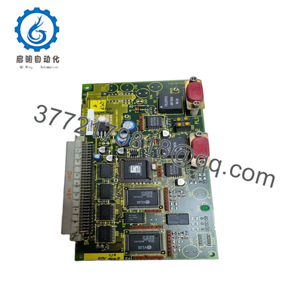
The Alstom GDS1017-4001 is a high-performance Field Local Processor (FLP) enhancement card designed for the Alspa GD3000E and DC3000 heavy industrial drive platforms. Engineered during the co-development eras of Cegelec and Converteam, this module operates at a 1 MHz execution frequency to enhance data throughput and synchronize real-time torque, velocity, and gate-firing calculations between the main processor rack and phase power assemblies. Its optimized processing layer ensures steady commutation limits, minimizing harmonic disturbance across critical high-capacity motor lines.
As an obsolete component no longer supported by the original manufacturer, the GDS1017-4001 represents a critical risk point regarding lead time variability. Sourcing this module as a New Surplus asset provides warehouse managers with a vital insurance policy, optimizing the system’s Total Cost of Ownership (TCO) by completely avoiding the exorbitant costs of unpredicted downtime. Opting for untouched surplus inventory removes the severe risks of thermal fatigue, hidden solder faults, and component drift that plague standard refurbished boards, guaranteeing long-term plant network stability.

- GDS1017-4001
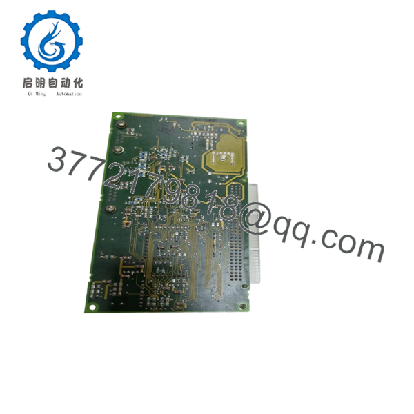
- GDS1017-4001
Installation & Configuration Guide
Stage 1: Pre-Installation (Prep & Safety)
- Implement complete plant lock-out/tag-out (LOTO) protocols on the host variable speed drive and its primary 3-phase isolation switchboards.
- Allow a minimum of 15 minutes for the drive’s internal capacitor banks to discharge completely, and verify a zero-voltage state with a rated multimeter.
- Wear a verified, grounded ESD wrist strap attached to an unpainted chassis node before handling any internal electronics.
- Document the old card configuration. Take clear photographs of all internal board DIP switch patterns, layout jumpers, and software revision stickers.
Stage 2: Removal
- Unfasten the card-retaining clips or faceplate locking screws on the drive control rack layer.
- Disconnect any front-facing ribbon connections or fiber optic communication cables, marking their positions for exact re-termination.
- Extract the GDS1017-4001 module from its slot guide tracks by pulling it straight outward with uniform, parallel pressure to protect the backplane pins.
- Place the removed card directly into a static-safe ESD shielding bag.
Stage 3: Installation (Clone & Seat)
- Unbox the new surplus GDS1017-4001 card within an ESD-cleared workbench area.
- Configure all physical board DIP switches and configuration jumper blocks to mirror the layout of the original module exactly.
- Slide the card smoothly along the chassis tracking lanes until the backplane interface seats completely into the main bus receiver.
- Secure all integrated retention hardware and reattach the diagnostic cables or front panel interface ribbons.
Stage 4: Power-On & Testing
- Conduct an insulation check and inspect all connections to ensure no short circuits are present on the local rack power rails.
- Apply logic control power to the drive assembly.
- Observe the initial boot sequence indicators on the board: verify that the system runs its internal self-tests, flashing standard power indicators without flagging a red fault or system configuration error code.
- Use your drive programming workspace to run a 1 MHz network handshake loopback verification, confirming smooth data transfer limits across the system.
Firmware/Software Versions & Upgrade Notes
The GDS1017-4001 requires precise firmware version alignment with the master drive control platform (such as GD3000E or DC3000 networks). This assembly typically operates on factory standard production build patterns (such as revision suffix ENU 00/16 A), which governs the 1 MHz communication bus timing limits.
When deploying a replacement card, avoid performing ad-hoc firmware upgrades or altering code profiles during emergency maintenance periods. Intermixing mismatched card revisions inside redundant configuration architectures can lead to immediate drive synchronization faults or protocol timeouts, causing the main inverter control line to trip. Always cross-reference the printed hardware build codes on the incoming board against your facility’s system archive file before restoring live operation.
Frequently Asked Questions (FAQ)
Q: What exactly does the 1MHz FLP designation mean on the GDS1017-4001 card? A: The 1 MHz FLP (Field Local Processor) indicates that this enhancement board operates a high-speed communication channel processing data loops at up to 1 million cycles per second. This sub-millisecond execution loop is essential for maintaining precision real-time firing commands and synchronization between the central Alspa controller and the power drive components.
Q: Why choose a New Surplus GDS1017-4001 instead of a refurbished or repaired option? A: Heavy industrial drive components are constantly exposed to high cabinet temperatures and electrical stress, which can cause internal component degradation over time. A refurbished board is a used assembly that has already incurred significant thermal wear, introducing a higher risk of unexpected failure. A New Surplus unit provides pristine, un-degraded component lifespans, offering optimal long-term system reliability and lower overall Total Cost of Ownership (TCO).
Q: Are Alstom, Cegelec, and Converteam versions of this module interchangeable? A: Yes. Through various corporate transitions, this exact module layout was manufactured under the Cegelec, Alstom, and Converteam brand names. As long as the primary model number (GDS1017-4001) and internal tracking reference (20X4249A4) match, the boards are fully form-factor compatible and functionally interchangeable.
Q: Can this enhancement card be replaced while the drive control rack is running? A: No. The GDS1017-4001 handles critical high-speed processing and system synchronization. Attempting to pull or insert this card while the backplane bus is energized can cause low-voltage arcing, corrupting live drive memory parameters or triggering an instant phase short fault on the main power lines. Always isolate control power before replacement.
Q: What type of warranty coverage do you provide for this obsolete drive card? A: Since the original equipment manufacturer has ended factory production and lifecycle support for this series, factory warranties are no longer available. To secure your facility’s operational safety, we back this New Surplus module with our own comprehensive 2-year warranty covering all electronic failures and processing defects.



